LiftMaster SW470 SW490 GL BOARD Manual - Page 24
Control Board Programming and Features, MOTOR LEARN FUNCTION FORCE PROFILE
 |
View all LiftMaster SW470 manuals
Add to My Manuals
Save this manual to your list of manuals |
Page 24 highlights
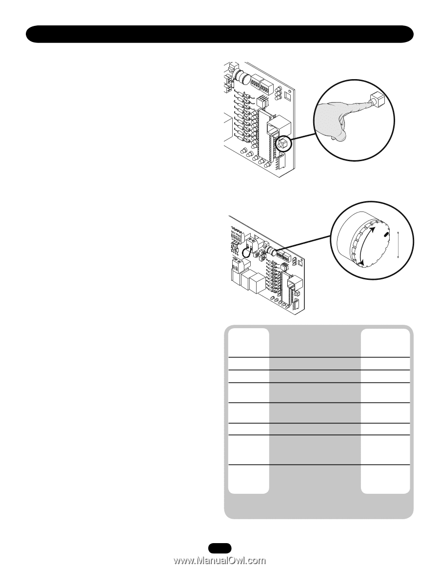
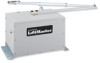
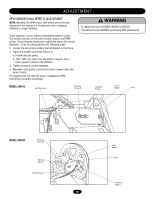
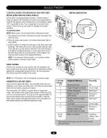
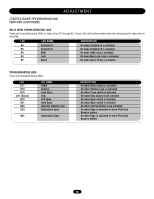
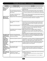
ADJUSTMENT CONTROL BOARD PROGRAMMING AND FEATURES MOTOR LEARN FUNCTION (FORCE PROFILE) This function is preprogrammed at factory. If either board or motor is replaced, the controller will need to be programmed to "LEARN" the specific motor RPM profile of your operator. Switch "S3" is provided for this. This is important for accurate force control. Failure to do so may result in improper and unsafe operation. To learn the motor: NOTE: Motor Learn must be performed in stand alone mode. 1. The operator must remain attached to the gate throughout the entire process. 2. Press the motor learn button. The yellow LED should start to flash rapidly. 3. Install a jumper on either the hard open or the hard close input terminals. The motor will run for a few seconds and then stop. If the LED goes out the motor is learned. If the unit activates a limit before completing the learn or some other error occurs, the LED will go back to on continuously. If this happens, try learning while running in the opposite direction. NOTE: It is important that the jumper is in constant contact while the gate is moving in learn mode. FORCE CONTROL Set the force control pot such that the unit will complete a full cycle of gate travel but can be reversed off an obstruction without applying an unreasonable amount of force. On most operators this will be around the middle of the range. MOTOR LEARN BUTTON Motor Learn Button (S3) FORCE CONTROL Force Control Min Max NOTE: For LED location refer to illustration on previous page. DIAGNOSTICS (LEDS AND CODES) There are three diagnostic LEDs. Two red LEDs (OLS, CLS) are indicators for the open and close limits. The LEDs are illuminated when the limit switch contacts are closed. The third amber LED (DIAG) is used to blink out diagnostic codes. The number is the count of the number of times the LED is on in an 8 second period. The LED is on for approximately 1/2 second and repeats every second until the number is reached. There will be a pause following each pulse cycle (1-6 pulses) to differentiate between the different diagnostic codes. LED Code Flashed OFF Diagnostic Meaning Normal operation Cleared By N/A 1 Single entrapment sensed Control Input 2 Double entrapment Hard Input* 3 Failed or no hall effect sensor Removal of problem 4 Exceed maximum motor Hard Input* run time 5 Limit fault Control Input 6 Loss of communications Removal of between master and problem second during run mode On No Flash Motor not learned Completion of Motor Learn Routine *Hard inputs include open override, close override and stop inputs. 24
-
 1
1 -
2
-
3
-
4
-
5
-
6
-
7
-
8
-
9
-
10
-
11
-
12
-
13
-
14
-
15
-
16
-
17
-
18
-
 19
19 -
 20
20 -
 21
21 -
 22
22 -
 23
23 -
 24
24 -
 25
25 -
 26
26 -
 27
27 -
 28
28 -
 29
29 -
30
-
31
-
32
-
33
-
34
-
35
-
36
-
37
-
38
-
39
-
40
 |
 |