LiftMaster SW470 SW490 GL BOARD Manual - Page 28
Troubleshooting, POSSIBLE CAUSES - gate operator troubleshoot
 |
View all LiftMaster SW470 manuals
Add to My Manuals
Save this manual to your list of manuals |
Page 28 highlights
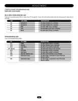
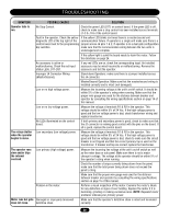
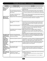
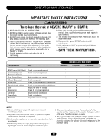
TROUBLESHOOTING SYMPTOM Operator fails to run. POSSIBLE CAUSES No Stop Control. SOLUTION Check the green LED (D17) on control board. If the green LED is off, check to make sure a stop control has been installed across terminals J1-3 & J1-5 of the control board. Fault in the operator. Check the yellow If the yellow LED blinks six times there is a master/second unit diagnostic LED at the top right of the communication failure. If operator is a single unit make sure there is a control board next to the programming jumper across J4 pins 1 & 2. If operator is in a dual gate configuration dip switches. make sure that the communication wiring between the two units is undamaged and complete. If the yellow light is solid the board needs to learn the motor. Follow the directions on page 24. An accessory is active or malfunctioning. Check the red input status LEDs, D11-D31. If any red LEDs are on, check the corresponding input. An installed accessory may be wired incorrectly or malfunctioning. Remove the accessory and test the operator. Improper J4 Connector Wiring (Master/Second). Stand-alone Operators: make sure there is a jumper installed across the J4 connector. Master/Second Operation: Make sure that the master/second wiring is installed correctly and is intact (not damaged). Low or no high voltage power. Measure the incoming voltage at the unit's on/off switch. It should be within 5% of the operator's rating when running. Make sure that the proper wire gauge was used for the distance between breaker and operator by consulting the wiring specifications section on page 14 of this manual. Low or no low voltage power. Measure the voltage at terminals R1 & R2 in the operator. This voltage should be within 5% of 24 Vac. If the high voltage power is good and the low voltage power is bad, check transformer wiring and replace transformer. No LEDs illuminated on the control board. If both primary and secondary power is good, check to make sure that the J2 connector is making good contact with the pins on the board. If all is good, replace the control board. The relays chatter when the operator begins to move. Low secondary (low voltage) power. Measure the voltage at terminals R1 & R2 in the operator. This voltage should be within 5% of 24 Vac. If the high voltage power is good and the low voltage power is bad, check to make sure the circuit breaker is not tripped and that the correct primary tap is used on the transformer. If breaker and tap are correct replace the transformer. The operator runs slow and/or trips the internal overload. Low primary (high voltage) power. Measure the incoming line voltage at the unit's on/off switch as well as the meter base or sub panel. Make sure there is not a major change in voltage. The voltage at the operator should be within 5% of the operator's rating when running. Check the number of amps currently being drawn from the panel, make sure that the total power being drawn does not exceed the panel's rating. Make sure that the proper wire gauge was used for the distance between breaker and operator by consulting the wiring specifications section on page 15 of this manual. Problem in the motor. Perform a visual inspection of the motor. Examine the motor's labels for any distortion or signs of over heating. Replace the motor if it is humming, grinding or making excessive noise. NOTE: Repeated motor problems indicate poor primary power. Motor runs but gate Damaged or improperly tensioned does not move. belt/drive chain. Make sure that the operator's belt/drive chain is intact and tensioned correctly. 28
-
 1
1 -
2
-
3
-
4
-
5
-
6
-
7
-
8
-
9
-
10
-
11
-
12
-
13
-
14
-
15
-
16
-
17
-
18
-
19
-
20
-
21
-
22
-
 23
23 -
 24
24 -
 25
25 -
 26
26 -
 27
27 -
 28
28 -
 29
29 -
 30
30 -
 31
31 -
 32
32 -
 33
33 -
34
-
35
-
36
-
37
-
38
-
39
-
40
 |
 |
