MSI 661FM2-LSR User Guide
MSI 661FM2-LSR - Motherboard - Micro ATX Manual
 |
UPC - 816909007343
View all MSI 661FM2-LSR manuals
Add to My Manuals
Save this manual to your list of manuals |
MSI 661FM2-LSR manual content summary:
- MSI 661FM2-LSR | User Guide - Page 1
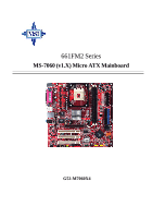
661FM2 Series MS-7060 (v1.X) Micro ATX Mainboard G52-M7060X4 i - MSI 661FM2-LSR | User Guide - Page 2
Manual with the instruction manual, may cause harmful interference to radio communications. Operation of this equipment in a residential area is likely to cause harmful interference, in which case the user responsible for compliance could void the user's authority to operate the equipment - MSI 661FM2-LSR | User Guide - Page 3
Corporation. PS/2 and OS®/2 are registered trademarks of International Business Machines Corporation. Microsoft is a registered trademark of Microsoft Corporation. Windows® 98/ 2000/NT/XP are registered trademarks of Microsoft Corporation. NVIDIA, the NVIDIA logo, DualNet, and nForce are registered - MSI 661FM2-LSR | User Guide - Page 4
1. Always read the safety instructions carefully. 2. Keep this User's Manual for future reference. 3. Keep this equipment away shock. 11. If any of the following situations arises, get the equipment checked by a service personnel: h The power cord or plug is damaged. h Liquid has penetrated into the - MSI 661FM2-LSR | User Guide - Page 5
Safety Instructions iv Chapter 1. Getting Started 1-1 Mainboard Specifications 1-2 Mainboard Layout 1-4 Chapter 2. Hardware Setup 2-1 Quick Components Guide 2-2 Central Processing Unit: CPU 2-3 CPU Core Speed Derivation Procedure 2-3 Memory Speed/CPU FSB Support Matrix 2-3 CPU Installation - MSI 661FM2-LSR | User Guide - Page 6
: JFP1 & JFP2 2-19 CD-In Connector: JCD1 2-20 Front Panel Audio Connector: JAUD1 2-20 Front USB Connectors: JUSB1 & JUSB2 2-21 SPDIF 2-23 AGP (Accelerated Graphics Port) Slot 2-23 PCI (Peripheral Component Interconnect) Slots 2-23 PCI Interrupt Request Routing 2-23 Chapter 3. BIOS Setup - MSI 661FM2-LSR | User Guide - Page 7
BIOS Utility 4-5 Create a RAID 0 (Stripe) Array for performance 4-8 Create a RAID 1 (Mirror) Array for performance 4-12 Create a JBOD Array for performance 4-16 Delete a RAID array 4-18 Installing Software 4-21 Install Driver in Windows XP/2000 4-21 Installation of SiS SATA RAID Driver - MSI 661FM2-LSR | User Guide - Page 8
Appendix: Using 4- or 6-Channel Audio A-1 Installing the Audio Driver A-2 Installation for Windows 98SE/ME/2000/XP A-2 Using 4- or 6-Channel Audio Function A-4 Using the Back Panel A-4 Testing the Connected Speakers A-9 Testing Each Speaker A-9 Playing KaraOK A-11 Playing KaraOK A-11 viii - MSI 661FM2-LSR | User Guide - Page 9
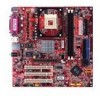
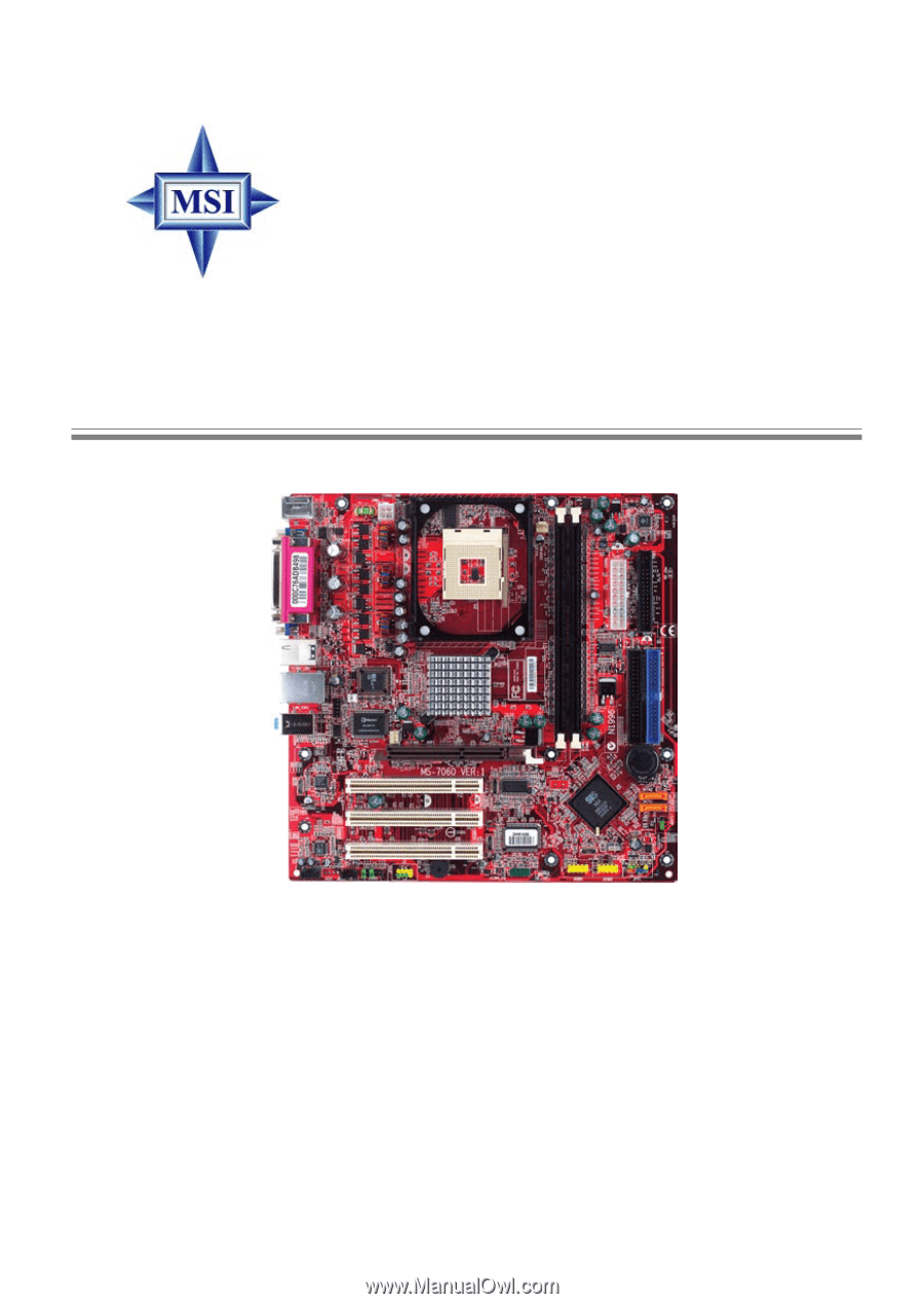
Hardware Setup Chapter 1. Getting Started Getting Started Thank you for purchasing 661FM2 Series (MS-7060 v1.X) Micro ATX mainboard. The 661FM2 series is based on SiS® 661FX & SiS® 964 chipsets for optimal system efficiency. Designed to fit the advanced Intel® Pentium 4 processor in the 478-pin - MSI 661FM2-LSR | User Guide - Page 10
& high quality 3D Graphic Accelerator - Supports AGP 8x/4x interface - Supports bi-directional 16-bit data bus with 1GHz bandwidth h SiS® 964 - Supports Dual IDE ATA 100/133 - Integrated audio controller with AC97 interface - Supports HyperTransport Technology - Advanced power management and - MSI 661FM2-LSR | User Guide - Page 11
audio performance requirement - Can support SPDIF out via a 3-pin SPDIF-Out pinheader. LAN h Fast Ethernet integrated in SiS® 964. h Realtek 8201BL LAN PHY. h IEEE 802.3 and 802.3x Standard Compatible h Supports ACPI v1.0b and PCI power management v1.1 Standard BIOS h 4MB Award BIOS with PNP BIOS - MSI 661FM2-LSR | User Guide - Page 12
ports JCI1 SiS 661FX Line-In Line-Out Mic JCOM1 Winbond W83697HF SYSFAN1 AGP Slot Realtek 8201BL PCI Slot 1 PCI Slot 2 Codec PCI Slot 3 JCD1 JSP1 JAUD1 JFP2 DIMM 1 DIMM 2 VIA VT6307 J1394_2 (Optional) BATT + SiS964 SATA2 SATA1 JBAT1 JUSB1 JUSB2 JFP1 661FM2 Series (MS-7060) v1 - MSI 661FM2-LSR | User Guide - Page 13
Chapter 2. Hardware Setup Hardware Setup This chapter tells you how to install the CPU, memory modules, and expansion cards, as well as how to setup the jumpers on the mainboard. It also provides the instructions on connecting the peripheral devices, such as the mouse, keyboard, etc. While doing - MSI 661FM2-LSR | User Guide - Page 14
MS-7060 Micro ATX Mainboard Quick Components Guide JPW1, p.2-9 CPUFAN1, p.2-15 CPU, p.2-3 DDR DIMMs, p.2-7 CONN1, p.2-9 Back Panel I/O, p.2-10 FDD1, p.2-15 IDE1, IDE2, p.2-16 JCOM1, p.2-18 JCI1, p.2-19 SYSFAN1, p.2-15 PCI Slots, p.2-23 JCD1, p.2-20 JSP1, p.2-21 JAUD1, p.2- - MSI 661FM2-LSR | User Guide - Page 15
Core/Bus ratio = 100MHz x 17 = 1.7 GHz Memory Speed/CPU FSB Support Matrix Memory FSB DDR 266 400 MHz OK 533 MHz OK 800 MHz OK DDR 333 OK OK OK DDR 400 OK OK OK MSI Reminds You... Overheating Overheating will seriously damage the CPU and system. Always make sure the cooling fan can - MSI 661FM2-LSR | User Guide - Page 16
MS-7060 Micro ATX Mainboard CPU Installation Procedures for Socket 478 1. Please turn off the power and unplug the power cord before installing the CPU. 2. Pull the lever sideways away from the socket. Make sure to raise the lever up to a 90-degree angle. 3. Look for the gold arrow. The - MSI 661FM2-LSR | User Guide - Page 17
important. To dissipate heat, you need to attach the CPU cooling fan and heatsink on top of the CPU. Follow the instructions below to install the Heatsink/Fan: 1. Locate the CPU and its retention mechanism on the motherboard. retention mechanism 2. Position the heatsink onto the retention - MSI 661FM2-LSR | User Guide - Page 18
MS-7060 Micro ATX Mainboard 5. Connect the fan power cable from the mounted fan to the 3-pin fan power connector on the board. fan power cable NOTES 2-6 - MSI 661FM2-LSR | User Guide - Page 19
size up to 2GB without ECC. To operate properly, at least one DIMM module must be installed. (For the updated supporting memory modules, please visit http://www.msi.com.tw/ program/products/mainboard/mbd/pro_mbd_trp_list.php ) DDR DIMM Slots (DDR 1~2) Introduction to DDR SDRAM DDR (Double Data Rate - MSI 661FM2-LSR | User Guide - Page 20
MS-7060 0 & 1) DDR 2 (Bank 2 & 3) Memory Module S/D S/D Maximum System Memory Supported S: Single Side D: Double Side Total Memory 64MB~1GB 64MB~1GB 64MB~2GB Installing DDR slot will automatically close. Volt Notch MSI Reminds You... You can barely see the golden finger if the module is - MSI 661FM2-LSR | User Guide - Page 21
Hardware Setup Power Supply The mainboard supports ATX power supply for the power system. Before This 12V power connector is used to provide power to the CPU. 3 4 1 2 JPW1 JPW1 Pin Definition PIN SIGNAL 1 GND 2 GND 3 12V 4 12V MSI Reminds You... Power supply of 300-watt (and above) - MSI 661FM2-LSR | User Guide - Page 22
MS-7060 Micro ATX Mainboard Back Panel The back panel provides the following connectors: Mouse Parallel 1394 (Optional) LAN L-in L-out Keyboard COM Port VGA Port USB Port USB Port MIC Mouse Connector The mainboard provides a standard PS/2® mouse mini DIN connector for attaching a PS/ 2® - MSI 661FM2-LSR | User Guide - Page 23
Hardware Setup Keyboard Connector The mainboard provides a standard PS/2® keyboard mini DIN connector for attaching a PS/2® keyboard. You can plug a PS/2® keyboard directly into this connector. Pin Definition 6 5 PIN SIGNAL DESCRIPTION 4 3 1 2 3 2 1 4 PS/2 Keyboard (6-pin Female) 5 6 - MSI 661FM2-LSR | User Guide - Page 24
MS-7060 Micro Send Ring Indicate VGA Connector The mainboard provides a DB 15-pin female connector to connect a VGA monitor. 5 1 Pin 1 2 3 4 15 11 5 VGA Connector,DB 15- range of devices, including consumer electronics audio/video (A/V) appliances, storage peripherals, other PCs, and portable - MSI 661FM2-LSR | User Guide - Page 25
Line In Line Out MIC MSI Reminds You... For advanced audio application, Realtek ALC 655 is provided to offer support for 6-channel audio operation and can turn rear audio connectors from 2-channel to 4-/6-channel audio. For more information on 6-channel audio operation, please refer to Appendix - MSI 661FM2-LSR | User Guide - Page 26
MS-7060 Micro ATX Mainboard Parallel Port Connector: LPT1 The mainboard provides a 25-pin female centronic connector as LPT. A parallel port is a standard printer port that supports Enhanced Parallel Port (EPP) and Extended Capabilities Parallel Port (ECP) mode. 13 1 25 14 Pin Definition PIN - MSI 661FM2-LSR | User Guide - Page 27
IR module and CPU/System/Power Supply FAN. Floppy Disk Drive Connector: FDD1 The mainboard provides a standard floppy disk drive connector that supports 360K, 720K, advantage of the CPU fan control. +12V SENSOR GND CPUFAN1 SENSOR +12V GND SYSFAN1 MSI Reminds You... Always consult the vendors - MSI 661FM2-LSR | User Guide - Page 28
MS-7060 disk drives, CD-ROM, 120MB Floppy (reserved for future BIOS) and other devices. These connectors support the provided IDE hard disk cable. IDE2 IDE1 IDE1 ( IDE Connector) IDE2 can also connect a Master and a Slave drive. MSI Reminds You... If you install two hard disks on cable, you must - MSI 661FM2-LSR | User Guide - Page 29
mainboard provides dual high-speed Serial ATA interface ports. The ports support 1st generation Serial ATA data rates of 150MB/s and are fully dust cover and connect to the hard disk devices Connect to SATA1 or SATA2 MSI Reminds You... Please do not fold the Serial ATA cable into 90-degree angle. - MSI 661FM2-LSR | User Guide - Page 30
MS-7060 Micro ATX Mainboard IEEE 1394 Connector: J1394_2 (Optional) The mainboard provides one IEEE1394 pin header that allows you to connect IEEE 1394 ports via an - MSI 661FM2-LSR | User Guide - Page 31
will record this status. To clear the warning, you must enter the BIOS setting and clear the status. GND CINTRU 1 JCI1 Front Panel Connectors: JFP1 switches and LEDs. It is compliant with Intel® Front Panel I/O Connectivity Design Guide. Speaker Power Power LED Switch JFP2 2 1 8 7 2 1 10 - MSI 661FM2-LSR | User Guide - Page 32
MS-7060 Micro ATX Mainboard CD-In Connector: JCD1 The connector is for CD-ROM audio connector. JCD1 R GND L Front Panel Audio Connector: JAUD1 The JAUD1 front panel audio connector allows you to connect to the front panel audio and is compliant with Intel® Front Panel I/O Connectivity Design Guide. - MSI 661FM2-LSR | User Guide - Page 33
pin headers JUSB1/JUSB2 that are compliant with Intel® I/O Connectivity Design Guide. USB 2.0 technology increases data transfer rate up to a maximum digital audio transmission. 1 3 JSP1 JSP1 Pin Definition PIN SIGNAL 1 VCCS 2 SPDIF0 3 GND Connected to JSP1 The JSP1 supports SPDIF - MSI 661FM2-LSR | User Guide - Page 34
MS-7060 Micro ATX Mainboard Jumpers The motherboard provides the following jumpers for you to set the computer's function. This section will explain how to change your motherboard data. Follow the instructions below to clear the data: JBAT1 1 3 3 1 Keep Data 1 Clear Data MSI Reminds You... You - MSI 661FM2-LSR | User Guide - Page 35
motherboard provides one AGP slot, three 32-bit PCI bus slots. AGP (Accelerated Graphics Port) Slot The AGP slot allows you to insert the AGP graphics card. AGP settings for the expansion card, such as jumpers, switches or BIOS configuration. PCI Slot PCI Interrupt Request Routing The IRQ, - MSI 661FM2-LSR | User Guide - Page 36
default settings for customized features. MSI Reminds You... 1. The items under each BIOS category described in this chapter are BIOS maker as A=AMI(R); W=AWARD(R) 2nd - 5th digit refers to the model number. 6th - 7th digit refers to the customer, MS=all standard customers. V1.1 refers to the BIOS - MSI 661FM2-LSR | User Guide - Page 37
MS-7060 Micro ATX Mainboard Entering Setup Power on the computer and the system will start POST (Power On Self Test) process. When the message below appears - MSI 661FM2-LSR | User Guide - Page 38
the appropriate keys to use and the possible selections for the highlighted item. Press to exit the Help screen. MSI Reminds You... The items under each BIOS category described in this chapter are under continuous update for better system performance. Therefore, the description may be slightly - MSI 661FM2-LSR | User Guide - Page 39
MS-7060 Micro ATX Mainboard The Main Menu Once you enter Award® BIOS CMOS Setup Utility, the Main Menu (figure your settings for power management. PNP/PCI Configurations This entry appears if your system supports PnP/PCI. PC Health Status This entry shows your PC health status. Frequency/Voltage - MSI 661FM2-LSR | User Guide - Page 40
Load Optimized Defaults Use this menu to load factory default settings into the BIOS for stable system performance operations. Set Supervisor Password Use this menu to set Supervisor Password. Set User Password Use this menu to set User Password. Save & Exit Setup Save changes to CMOS and exit setup - MSI 661FM2-LSR | User Guide - Page 41
MS-7060 day month date year Day of the week, from Sun to Sat, determined by BIOS. Read-only. The month from Jan. through Dec. The date from 1 adjusted by users. Time The time format is . IDE Primary/Secondary Master/Slave Press PgUp/ or PgDn/ to select [Manual], [None - MSI 661FM2-LSR | User Guide - Page 42
BIOS Setup If you select [Manual], related information is asked to be entered to the The setting controls the type of video adapter used for the primary monitor of the system. Setting options: [EGA/VGA], [CGA 40], [CGA 80], [MONO]. Halt On The setting determines whether the system will stop if an - MSI 661FM2-LSR | User Guide - Page 43
MS-7060 Micro ATX Mainboard Advanced BIOS Features Quick Boot Setting the item to [Enabled] allows the 1st/2nd/3rd Boot Device The items allow you to set the sequence of boot devices where BIOS attempts to load the disk operating system. Boot Other Device Setting the option to [Enabled] allows - MSI 661FM2-LSR | User Guide - Page 44
MSI Reminds Support in SiS users to use the arrow keys on the numeric keypad. Setting options: [On], [Off]. CPU L1 & L2 Cache The item allows you to turn on or off CPU's internal (L1) and external (L2) cache. Setting options: [Enabled], [Disabled]. CPU L3 Cache This item is only for CPU that supports - MSI 661FM2-LSR | User Guide - Page 45
system requires ALL of the following platform Components: *CPU: An Intel® Pentium® 4 Processor with HT Technology; *Chipset: A chipset that supports HT Technology; *BIOS: A BIOS that supports HT Technology and has it enabled; *OS: Only Microsoft® Windows 2000 and XP can support HT technology. 3-10 - MSI 661FM2-LSR | User Guide - Page 46
Press and the following sub-menu appears: Current CPU/DRAM/DDR Frequency These items allow you to view the current CPU/DRAM/DDR frequency. Performance Mode This setting particularly provided by SiS gives the proper suggestion for user to set timing. The Timings programmed into this register - MSI 661FM2-LSR | User Guide - Page 47
MS-7060 Micro ATX Mainboard DRAM Timing Control This field allows you to select the DRAM timing setting. Setting to [By SPD] enables Max Memclock (Mhz) automatically to be determined by SPD. Selecting [Manual] allows users to configure these fields manually. DRAM CAS Latency When the DRAM Timing - MSI 661FM2-LSR | User Guide - Page 48
[512MB]. AGP Fast Write Support This option [Enabled] or [Disabled] the AGP Fast Write feature. The Fast Write technology allows the CPU to write rate of AGP. Setting options: [Auto], [1X], [2X], [4X], [8X]. OnChip AGP Control Press and the following sub-menu appears: VGA Shared Memory - MSI 661FM2-LSR | User Guide - Page 49
MS-7060 Micro ATX Mainboard Integrated Peripherals SiS OnChip IDE Device Press < driver (Windows ME, XP or a third-party IDE bus master driver). If your hard drive and your system software both support Ultra DMA/33, Ultra DMA/66, Ultra DMA/100 and Ultra DMA/133, select [Auto] to enable BIOS support - MSI 661FM2-LSR | User Guide - Page 50
in the operating system that does not support or does not have any USB driver installed, such as DOS and SCO Unix. SiS AC97 Audio [Auto] allows the mainboard to detect whether an audio device is used. If an audio device is detected, the onboard AC97 (Audio Codec'97) controller will be enabled; if - MSI 661FM2-LSR | User Guide - Page 51
MS-7060 LPT1B)/Serial Port 2 (JCOM1). Selecting [Auto] allows BIOS to automatically determine the correct base I/O port address. Mode Use DMA." At this time, the user can choose between DMA channel [3] or [1]. VGA card is your primary graphics adapter. Setting options: [PCI Slot], [AGP]. 3-16 - MSI 661FM2-LSR | User Guide - Page 52
-aware, such as Windows 98SE/ 2000/ME, select [Enabled]. Setting options: [Enabled], [Disabled]. Sleep State This item specifies the power saving modes for ACPI function. Options are: [S1/POS] The S1 sleep mode is a low power state. In this state, no system context is lost (CPU or chipset) and - MSI 661FM2-LSR | User Guide - Page 53
MS-7060 Micro ATX Mainboard MODEM Use IRQ This setting names the interrupt request (IRQ will be shut off. Setting options: [Disabled], [1-15 Mins]. Power Button Function This feature allows users to configure the Power Button function. Setting options: [Power Off] The power button functions as a - MSI 661FM2-LSR | User Guide - Page 54
Events Press and the following sub-menu appears: BIOS Setup IRQ [3-7, 9-15], NMI; IRQ 8 Break system. Setting options: [Click], [Move & Click], [Disabled]. MSI Reminds You... S3-related functions described in this section are available only when your BIOS supports S3 sleep mode. 3-19 - MSI 661FM2-LSR | User Guide - Page 55
MS-7060 Micro ATX Mainboard Resume By Alarm The field is used to enable or disable the function of Resume By Alarm. Setting options: [Disabled], [Enabled]. Month - MSI 661FM2-LSR | User Guide - Page 56
CPU itself uses when communicating with its special components. This section covers some very technical items and it is strongly recommended that only experienced users The Award Plug and Play BIOS has the capacity to automatically such as Windows® 98/ 2000. If you set this field to [Manual], choose - MSI 661FM2-LSR | User Guide - Page 57
MS-7060 Micro ATX Mainboard IRQ Resources The items are adjustable only when Resources Controlled By is set to Manual. Press and you will enter the sub-menu of the items. IRQ Resources list IRQ 3/4/5/7/9/10/11/12/14/15 for users to set each IRQ a type depending on the type of device using - MSI 661FM2-LSR | User Guide - Page 58
BIOS Setup PC Health Status This section shows the status of your CPU, fan, overall system status, etc. Monitor automatically return to [Enabled] later. Setting options: [Enabled], [Reset], [Disabled]. System/CPU Temperature, CPU/System FAN Speed, Vcore, 3.3 V, +5 V, +12 V, -12 V, VBAT(V), 5VSB - MSI 661FM2-LSR | User Guide - Page 59
MS-7060 Micro ATX Mainboard Frequency/Voltage Control Use this menu to specify your settings for frequency/voltage control. CPU Clock Ratio End users can overclock the processor (only if the processor supports so) by specifying the CPU motherboard do not have any EMI problem, leave the setting at [ - MSI 661FM2-LSR | User Guide - Page 60
Defaults The two options on the main menu allow users to restore all of the BIOS settings to the default Fail-Safe or Optimized values. the mainboard. The Fail-Safe Defaults are the default values set by the BIOS vendor for stable system performance. When you select Load Fail-Safe Defaults, a - MSI 661FM2-LSR | User Guide - Page 61
MS-7060 Micro ATX Mainboard Set Supervisor/User is required in the Security Option of the Advanced BIOS Feature menu. If the Security Option is set to MSI Reminds You... About Supervisor Password & User Password: Supervisor password: Can enter and change the settings of the setup menu. User - MSI 661FM2-LSR | User Guide - Page 62
SATA RAID The optional southbridge SiS964 SATA controller only support two Serial ATA on two independent ports. Serial ATA (SATA) is the latest generation of the ATA interface. SATA files. Span would increase the logic hard disk space. MSI Reminds You... All the information/volumes listed in your - MSI 661FM2-LSR | User Guide - Page 63
MS-7060 Micro ATX Mainboard Introduction System Requirement Operating System Support Microsoft Windows 98 Second Edition Microsoft Windows ME Microsoft Windows 2000 Professional and Server Microsoft Windows . The hard drives are simply hooked up in series. This expands the capacity of your drive and - MSI 661FM2-LSR | User Guide - Page 64
Introduction to SiS964 SATA RAID RAID 0 (Striping array) Any combination to 2, 3 or 4 Hard disks would combine to a stripe system. HDD Population Rules for RAID 0 (Striping) Ultra ATA (Master) Ultra - MSI 661FM2-LSR | User Guide - Page 65
MS-7060 Micro ATX Mainboard System BIOS Setup Power on the computer and the system will start POST (Power On Self Test) process. When the message below appears on the screen, press key to enter Setup. For Award BIOS: Press DEL to enter SETUP If the message disappears before you respond and you - MSI 661FM2-LSR | User Guide - Page 66
Introduction to SiS964 SATA RAID BIOS Configuration Starting BIOS Utility 1. Boot your system. If this is the first time you have booted with the SiS964 and the drives installed, the BIOS will display the following screen: Silicon Integrated Systems Corp. RAID BIOS Setting Utility v1.04_964 (c) 2003 - MSI 661FM2-LSR | User Guide - Page 67
MS-7060 Micro ATX Mainboard 2. Press keys to display the SiS964 Utility Main Menu. 3. Press to display the RAID setup menu below. This is the fastest - MSI 661FM2-LSR | User Guide - Page 68
Introduction to SiS964 SATA RAID [b]. No available disk existing but have RAID existing: [c]. Available disks and RAID existing simultaneously: 4-7 - MSI 661FM2-LSR | User Guide - Page 69
MS-7060 Micro ATX Mainboard [d]. Available disk is not enough to create RAID: Create a RAID 0 (Stripe) Array for performance To create an array for best performance, please follow these steps: 1. Press to start creating a RAID array. 2. Press and to select RAID 0. 4-8 - MSI 661FM2-LSR | User Guide - Page 70
Introduction to SiS964 SATA RAID 3. You will have two selections to create a RAID 0 array. The default value is . auto creating will be shown on step 6. Besides, you also can select Manual Create, see following steps. 4. Press -- keys and to select Block Size. (Default: 64K) 4-9 - MSI 661FM2-LSR | User Guide - Page 71
MS-7060 Micro ATX Mainboard 5. Use < > < > to select disk , and press to select disk, to exit. When you press on the disk you wanted, the - MSI 661FM2-LSR | User Guide - Page 72
Introduction to SiS964 SATA RAID 7. Starting splitting action, the following frame will be shown. 8. After all steps finished, press until escape the setup menu and RAID 0 array will be shown on the top of the main frame. 4-11 - MSI 661FM2-LSR | User Guide - Page 73
MS-7060 Micro ATX Mainboard 9. Press until exit this BIOS utility and the red message frame will show. Press and to save changes. 10. Once the array has been created, you will need to - MSI 661FM2-LSR | User Guide - Page 74
Introduction to SiS964 SATA RAID 3. You will have two selections to create a RAID 1 array. The default value is . If you select Auto Create, you can create a RAID 1 array faster and easier. The result after creating will be shown on step 5. Besides, you also can select Manual Create, see - MSI 661FM2-LSR | User Guide - Page 75
MS-7060 Micro ATX Mainboard 5. Next, you will see a message "Duplicate the SOURCE(Disk x) data to RAID disks?". Press and to create RAID 1 array only or - MSI 661FM2-LSR | User Guide - Page 76
Introduction to SiS964 SATA RAID 7. After all steps finished, press until escape the setup menu and RAID 1 array will be shown on the top of the main frame. 8. Press until exit this BIOS utility and the red message frame will show as the same as the creation of the RAID 0 array. Press - MSI 661FM2-LSR | User Guide - Page 77
MS-7060 Micro ATX Mainboard Create a JBOD Array for performance To create a JBOD array for best performance, please follow these steps: 1. Press JBOD array faster and easier. The result after creating will be shown on step 5. Besides, you also can select Manual Create, see following steps. 4-16 - MSI 661FM2-LSR | User Guide - Page 78
Introduction to SiS964 SATA RAID 4. Use< > < > to select disk , and press to select disk, to exit. When you press on the disk you wanted, the RAID Type - MSI 661FM2-LSR | User Guide - Page 79
MS-7060 Micro ATX Mainboard Delete a RAID array 1. After enter the SiS964 Utility Main Menu, press to display the RAID setup menu below. This is the fastest - MSI 661FM2-LSR | User Guide - Page 80
Introduction to SiS964 SATA RAID 3. Press to select the RAID array that you want to delete. And a message "Are you sure to delete this RAID?" will show on - MSI 661FM2-LSR | User Guide - Page 81
MS-7060 Micro ATX Mainboard 5. Press until escape the BIOS Utility, and the red message frame will show on it. 6. Press and to save all changes. 4-20 - MSI 661FM2-LSR | User Guide - Page 82
Introduction to SiS964 SATA RAID Installing Software Install Driver in Windows XP / 2000 MSI Reminds You... If you would like to install windows to any RAID set, you should create RAID from BIOS RAID setting Utility first and then follow the steps below. h New Windows XP / 2000 Installation The - MSI 661FM2-LSR | User Guide - Page 83
appear. Installation of SiS SATA RAID Driver SiS RAID driver supports Microsoft Windows XP/2000/ME/98SE. South Bridge SiS964 SATA controller support Serial ATA w/ RAID0, RAID 1 and JBOD by installing SiS RAID driver. Insert the MSI CD and click on the SiS SATA RAID Driver to install the software - MSI 661FM2-LSR | User Guide - Page 84
Function Appendix: Using 4- or 6-Channel Audio Function The motherboard is equipped with Realtek ALC655 chip, which provides support for 6-channel audio output, including 2 Front, 2 Rear, 1 Center and 1 Subwoofer channel. ALC655 allows the board to attach 4 or 6 speakers for better surround sound - MSI 661FM2-LSR | User Guide - Page 85
MS-7060 Micro ATX Mainboard Installing the Audio Driver You need to install the driver for Realtek ALC655 chip to function properly before you can get access to 4-/6-channel audio operations. Follow the procedures described below to install the drivers for different operating systems. Installation - MSI 661FM2-LSR | User Guide - Page 86
Using 4- or 6-Channel Audio Function 3. Click Next to start installing files into the system. 4. Click Finish to restart the system. Select this option A-3 - MSI 661FM2-LSR | User Guide - Page 87
MS-7060 Micro ATX Mainboard Using 4- or 6-Channel Audio Function After installing the audio driver, you are able to use the 4-/6-channel audio feature now. To enable 4- or 6-channel audio operation, first connect 4 or 6 speakers to the appropriate audio audio icon the screen. from the window tray - MSI 661FM2-LSR | User Guide - Page 88
Using 4- or 6-Channel Audio Function 3 2 4 5 6 A-5 - MSI 661FM2-LSR | User Guide - Page 89
MS-7060 Micro ATX Mainboard Connecting the Speakers When you have set the Multi-Channel Audio Function mode properly in the software utility, connect your speakers to the correct phone jacks in accordance with the setting in software utility. „ 2-Channel Mode - MSI 661FM2-LSR | User Guide - Page 90
jacks on the back panel always provide 2-channel analog audio output function, however these audio jacks can be transformed to 4- or 6channel analog audio jacks by selecting the corresponding multi-channel operation from No. of Speakers. Refer to the following diagram and caption for the function - MSI 661FM2-LSR | User Guide - Page 91
MS-7060 Micro ATX Mainboard „ 6-Channel Mode for 6-Speaker Output Refer to the Out func- tion when 6-Channel Mode for 3 6-Speaker Output is selected. MSI Reminds You... If the Center and Subwoofer speaker exchange their audio channels when you play video or music on the computer, a converter may - MSI 661FM2-LSR | User Guide - Page 92
the audio icon screen. from the window tray at the lower-right corner of the 2. Click the Speaker Test tab. 3. The following window appears. Front Right Rear Right Rear Left Subwoofer MSI Reminds You... 6 speakers appear on the "Speaker Test" window only when you select "6-Channel Mode" in - MSI 661FM2-LSR | User Guide - Page 93
MS-7060 Micro ATX Mainboard 4. While you are testing the speakers in 6-Channel Mode, if the sound coming from the center speaker and subwoofer is swapped, you should select Swap Center/ Subwoofer Output to readjust these two channels. Select this function A-10 - MSI 661FM2-LSR | User Guide - Page 94
voice (lyrics) and leave melody for you to sing the song. Note that this function applies only for 2-channel audio operation. Playing KaraOK 1. Click the audio icon screen. from the window tray at the lower-right corner of the 2. In the Sound Effect tab, select Voice Cancellation under "KaraOK
-
 1
1 -
 2
2 -
 3
3 -
 4
4 -
 5
5 -
 6
6 -
 7
7 -
8
-
9
-
10
-
11
-
12
-
13
-
14
-
15
-
16
-
17
-
18
-
19
-
20
-
21
-
22
-
23
-
24
-
25
-
26
-
27
-
28
-
29
-
30
-
31
-
32
-
33
-
34
-
35
-
36
-
37
-
38
-
39
-
40
-
41
-
42
-
43
-
44
-
45
-
46
-
47
-
48
-
49
-
50
-
51
-
52
-
53
-
54
-
55
-
56
-
57
-
58
-
59
-
60
-
61
-
62
-
63
-
64
-
65
-
66
-
67
-
68
-
69
-
70
-
71
-
72
-
73
-
74
-
75
-
76
-
77
-
78
-
79
-
80
-
81
-
82
-
83
-
84
-
85
-
86
-
87
-
88
-
89
-
90
-
91
-
92
-
93
-
94
 |
 |
G52-M7060X4
661FM2 Series
MS-7060 (v1.X) Micro ATX Mainboard