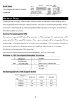
MSI 865PE NEO2-V User Guide - Page 11
Memory, Power Supply, ATX 20-Pin Power Connector: ATX1, ATX 12V Power Connector: JPW1, Floppy Disk - cpu support
 |
UPC - 816909005813
View all MSI 865PE NEO2-V manuals
Add to My Manuals
Save this manual to your list of manuals |
Page 11 highlights
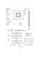
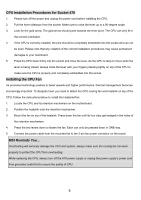
Memory The mainboard provides 2/3 slots for 184-pin, 2.5V DDR DIMM modules and supports the memory size up to 2 GB/3GB without ECC. You can install DDR266/DDR333/DDR400 DDR SDRAM modules on the DDR DIMM slots. To operate properly, at least one DIMM module must be installed. (For the updated supporting memory modules, please visit http://www.msi.com.tw/program/products/mainboard/mbd/pro_mbd_trp_list.php.) 1. The DDR DIMM has only one notch on the center of module. The module will only fit in the right orientation. Vo l t Notc h 2. Insert the DIMM memory module vertically into the DIMM slot. Then push it in until the golden finger on the memory module is deeply inserted in the socket. 3. The plastic clip at each side of the DIMM slot will automatically close. Power Supply The mainboard supports ATX power supply for the power system. Before inserting the power supply connector, always make sure all components installed properly and ensure no damage to be caused. ATX 20-Pin Power Connector: ATX1 This connector allows you to connect to an ATX power supply. To 5V GND GND GND 3. 3V 5V - 5V GN D PS_ ON -12 V connect to the ATX power supply, make sure the plug of the power 20 11 supply is inserted in the proper orientation and the pins are aligned. 10 1 Then push down the power supply firmly into the connector. 12 5V V _ SB GND PW_O K 5V GND 5V GND 3. 3. 3V 3V ATX 12V Power Connector: JPW1 This 12V power connector is used to provide power to the CPU. Floppy Disk Drive Connector: FDD1 12 V GND 34 12 12 V GND The mainboard provides a standard floppy disk drive connector that supports 360K, 720K, 1.2M, 1.44M and 2.88M floppy disk types. 7
-
 1
1 -
2
-
3
-
4
-
5
-
 6
6 -
 7
7 -
 8
8 -
 9
9 -
 10
10 -
 11
11 -
 12
12 -
 13
13 -
 14
14 -
 15
15 -
 16
16 -
17
-
18
-
19
-
20
-
21
-
22
-
23
-
24
-
25
-
26
-
27
-
28
-
29
-
30
-
31
-
32
-
33
-
34
-
35
-
36
-
37
-
38
-
39
-
40
-
41
-
42
-
43
-
44
-
45
-
46
-
47
-
48
-
49
-
50
-
51
-
52
-
53
-
54
-
55
-
56
-
57
-
58
-
59
-
60
-
61
-
62
-
63
-
64
-
65
-
66
-
67
-
68
-
69
-
70
-
71
-
72
-
73
-
74
-
75
-
76
-
77
-
78
-
79
-
80
-
81
-
82
-
83
-
84
-
85
-
86
-
87
-
88
-
89
-
90
-
91
-
92
-
93
-
94
-
95
-
96
-
97
-
98
-
99
-
100
-
101
-
102
-
103
-
104
-
105
-
106
-
107
-
108
 |
 |
