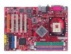
MSI 865PE NEO2-V User Guide - Page 12
CD-In Connector: CD1, S-Bracket Connector: JSP1 Optional, Fan Power Connectors: CPUFAN1/SYSFAN1, IDE
 |
UPC - 816909005813
View all MSI 865PE NEO2-V manuals
Add to My Manuals
Save this manual to your list of manuals |
Page 12 highlights
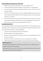
CD-In Connector: CD1 G ND The connector is for CD-ROM audio connector. R L S-Bracket Connector: JSP1 (Optional) The connector allows you to connect a S-Bracket for Sony & Philips Digital Interface SO UT -R SPD FO SOUT -L VD D3 GND 2 1 VC C5 12 11 G ND SPDF O (SPDIF). The S-Bracket offers 2 SPDIF jacks for digital audio transmission (one for GND CET-OU T LF E -OUT optical fiber connection and the other for coaxial), and 2 analog Line-Out jacks for 4-channel audio output. To attach the fiber-optic cable to optical SPDIF jack, you need to remove the plug from the jack first. The two SPDIF jacks support SPDIF output only. +12V Fan Power Connectors: CPUFAN1/SYSFAN1 GND The CFAN1 (processor fan) and SFAN1 (system fan) support system cooling fan SENSOR with +12V. They support three-pin head connector. When connecting the wire to the connectors, always take note that the red wire is the positive and should be connected to the +12V, the black wire is Ground and should be connected to GND. If the mainboard has a System Hardware Monitor chipset on-board, you must use a specially designed fan with speed sensor to take advantage of the CPU fan control. MSI Reminds You... 1. Always consult the vendors for proper CPU cooling fan. 2. CPUFAN1 supports the fan control. You can install the PC Alert utility that will automatically control the CPU fan speed according to the actual CPU temperature. IDE Connectors: IDE1 & IDE2 The mainboard has a 32-bit Enhanced PCI IDE and Ultra DMA 33/66/100 controller that provides PIO mode 0~5, Bus Master, and Ultra DMA 33/66/100 function. You can connect up to four hard disk drives, CD-ROM, 120MB Floppy and other devices. These connectors support the provided IDE hard disk cable. IDE1 (Primary IDE Connector): The first hard drive should always be connected to IDE1. IDE1 can connect a Master and a Slave drive. You must configure second hard drive to Slave mode by setting the jumper accordingly. IDE2 (Secondary IDE Connector): IDE2 can also connect a Master and a Slave drive. MSI Reminds You... If you install two hard disks on cable, you must configure the second drive to Slave mode by setting its jumper. Refer to the hard disk document supplied by hard disk vendors for jumper setting instructions. 8
-
 1
1 -
2
-
3
-
4
-
5
-
6
-
 7
7 -
 8
8 -
 9
9 -
 10
10 -
 11
11 -
 12
12 -
 13
13 -
 14
14 -
 15
15 -
 16
16 -
 17
17 -
18
-
19
-
20
-
21
-
22
-
23
-
24
-
25
-
26
-
27
-
28
-
29
-
30
-
31
-
32
-
33
-
34
-
35
-
36
-
37
-
38
-
39
-
40
-
41
-
42
-
43
-
44
-
45
-
46
-
47
-
48
-
49
-
50
-
51
-
52
-
53
-
54
-
55
-
56
-
57
-
58
-
59
-
60
-
61
-
62
-
63
-
64
-
65
-
66
-
67
-
68
-
69
-
70
-
71
-
72
-
73
-
74
-
75
-
76
-
77
-
78
-
79
-
80
-
81
-
82
-
83
-
84
-
85
-
86
-
87
-
88
-
89
-
90
-
91
-
92
-
93
-
94
-
95
-
96
-
97
-
98
-
99
-
100
-
101
-
102
-
103
-
104
-
105
-
106
-
107
-
108
 |
 |
