Mackie 1604-VLZ Pro Owner's Manual - Page 22
Output Description, Main Mix Fader, VLZ Mix Architecture, Subgroup Faders, Assign To Main - price
 |
View all Mackie 1604-VLZ Pro manuals
Add to My Manuals
Save this manual to your list of manuals |
Page 22 highlights
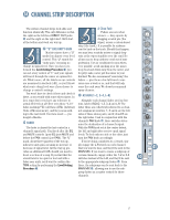
OUTPUT SECTION DESCRIPTION 1604-VLZ PRO 12V 16-CHANNEL MIC/ LINE MIXER 0.5A WITH PREMIUM XDRTM MIC PREAMPLIFIERS LAMP U U U 1 +10 U 1 +20 U 1 TO AUX SEND 1 +15 EFFECTS TO U MONITORS OO OO OO OO OO OO 2 +10 AUX SEND 2 +20 U 2 TO AUX SEND 2 +15 ASSIGN OPTIONS 1 3 OO OO SOLO 2 +20 U MAIN MIX 1-2 TO SUBS 3-4 SOLO 4 PHAN PWR C-R / PHNS RETURNS +20 ONLY SOLO STEREO AUX RETURN OO MAX CTL ROOM / PHONES TAPE SUBS 1-2 SUBS 3-4 MAIN MIX CTL ROOM SOURCE U LEFT RIGHT 0 dB=0 dBu 28 +20 10 TAPE IN 7 OO 4 TAPE TO 2 MAIN MIX 0 2 OO 4 MAX SOLO LEVEL SET 7 10 MODE NORMAL (AFL) LEVEL SET (PFL) 20 30 RUDE SOLO LIGHT ASSIGN TO MAIN MIX LEFT RIGHT 1 LEFT RIGHT 2 LEFT RIGHT 3 LEFT RIGHT 4 dB 10 PHONES MAIN MIX dB 10 5 5 U U 5 5 10 10 20 20 30 30 40 40 50 50 60 60 OO OO You've just learned about the input channels and how the signals get in and out. The signals come in via MIC and LINE input jacks, are manipulated by the channels, and then sent to the output section. In the output section, things get a bit more complicated, so put on your thinking caps. MAIN MIX FADER This fader controls the levels of signals sent to the MAIN OUT 1/4" TRS jacks and TAPE OUTPUT RCA jacks . All channels and AUX RETURNs that are assigned to the MAIN MIX, not muted and not turned fully down will appear at the MAIN OUT. Before the main mix gets to this fader, the signals pass through the MAIN INSERT . The MAIN MIX signals are off with the fader fully down, the "U" marking is unity gain, and fully up provides 10dB additional gain. This additional gain will typically never be needed, but once again, it's nice to know it's there. The fader itself is a stereo version of the channel and subgroup faders - same supersmooth custom taper, same dead silence when turned fully down. This is the fader to pull down at the end of the song when you want "The Great Fade-Out." VLZ MIX ARCHITECTURE When designing a mixing circuit, the lowest noise and best crosstalk specs are achieved by using Very Low Impedance (VLZ). To implement VLZ in a mixer, the power supply must be able to deliver plenty of current to the circuitry. That's why those "wall wart" mixers are often noisy - they can't power a VLZ circuit. 22 At Mackie, audio quality is much more important than the price of wall warts. All of our mixers now employ VLZ and built-in power supplies that deliver more than enough current, resulting in sonic specifications that rival consoles upwards of $50,000! SUBGROUP FADERS As you might expect, these faders control the levels of signals sent to the SUB OUTS. All channels that are assigned to subgroups, not muted and not turned fully down will appear at the SUB OUTS. Unlike the MAIN OUT, the subgroup signals do not pass through an insert jack on their way to the subgroup faders. That's no problem - should you want to send these signals through a serial effects processor, simply patch from the SUB OUTS to the effect's input, and from the effect's output to whatever the final destination is, usually a multitrack recorder. The subgroup signals is off when its fader is fully down, the "U" marking is unity gain, and fully up provides 10dB additional gain. Remember that if you're treating two subgroups as a stereo pair, subgroup 1 and 2 for example, make sure that both subgroup faders "ride" together, to maintain the left/right balance. ASSIGN TO MAIN MIX One popular use of the subgroups is to use them as master faders for a group of channels on their way to the MAIN MIX. Let's say you've got a drum kit hogging up seven channels and you're going to want to fade them out at a different rate than the other channels. You don't want to try that with seven hands or seven fingers, so just un-assign these channels from L-R, reassign them to subgroup 1-2, engage the ASSIGN TO MAIN MIX, LEFT on subgroup 1 and the ASSIGN TO MAIN MIX, RIGHT on subgroup 2. Now you can ride the entire stereo drum mix with two faders - 1 and 2. If you engage just one ASSIGN TO MAIN MIX switch per subgroup (LEFT or RIGHT), the signal sent to the MAIN MIX will be the same level as the SUB OUTS. If you want the subgroup to appear in the center of the main mix, engage both the ASSIGN TO MAIN MIX, LEFT and ASSIGN TO MAIN MIX, RIGHT switches. The signal will be sent to both sides, and will be attenuated just enough to preserve constant loudness , just like the channel PAN knobs when set center.
-
 1
1 -
2
-
3
-
4
-
5
-
6
-
7
-
8
-
9
-
10
-
11
-
12
-
13
-
14
-
15
-
16
-
 17
17 -
 18
18 -
 19
19 -
 20
20 -
 21
21 -
 22
22 -
 23
23 -
 24
24 -
 25
25 -
 26
26 -
 27
27 -
28
-
29
-
30
-
31
-
32
-
33
-
34
-
35
-
36
-
37
-
38
-
39
-
40
 |
 |
