Mackie CR1604 Modifications - Page 6
-VLZ PRO Modifications, Pre-Fader Mod (Aux To Monitor)
 |
View all Mackie CR1604 manuals
Add to My Manuals
Save this manual to your list of manuals |
Page 6 highlights
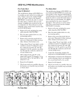
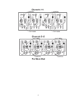
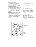
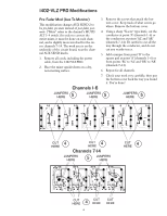
1402-VLZ PRO Modifications Pre-Fader Mod (Aux To Monitor) This modification changes AUX SEND 2 to be pre-fader, pre-mute instead of post-fader, postmute. ("Mute" refers to the channel's MUTE/ ALT 3-4 switch.) In order to convert the entire mixer, it must be done on each channel, and is slightly more involved for the stereo channels 7-14. The work area is on the underside of the circuit board, near the channel AUX SEND knobs. 1. Remove all cords, including the power cable, from the 1402-VLZ PRO. 2. Place the mixer upside-down on a dry, non-marring surface. 3. Remove the screws that attach the bottom cover. Keep track of what screws go where. Remove the bottom cover. 4. Using a sharp "X-acto" type knife, cut the conductor at point 'A' (channels 1-6) or the conductors at points 'AL' and 'AR' (channels 7-14). Be careful to cut all the way through the conductor, and do not cut any nearby traces. 5. Add a jumper from point 'B' to the square pad at point 'A' (channels 1-6) or from points 'BL' to 'AL' and 'BR' to 'AR' (channels 7-14). 6. Repeat for all channels. 7. Check your work very carefully, then put the bottom cover back the way you found it. You're done! Channels 1-6 JUMPERS HERE 5 JUMPERS HERE 5 JUMPERS HERE 5 CUT HERE 4 CUT 4 HERE Channels 7-14 JUMPERS HERE 5 JUMPERS HERE CUT 4 HERE CUT HERE 4 6 CUT HERE CUT HERE
-
 1
1 -
 2
2 -
 3
3 -
 4
4 -
 5
5 -
 6
6 -
 7
7 -
 8
8 -
 9
9 -
 10
10 -
 11
11 -
 12
12 -
13
-
14
-
15
-
16
 |
 |
