Mackie CR1604 Modifications - Page 7
Pre-Mute Mod - pro
 |
View all Mackie CR1604 manuals
Add to My Manuals
Save this manual to your list of manuals |
Page 7 highlights
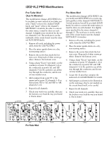
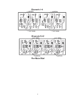
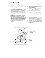
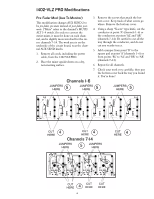
Pre-Mute Mod This modification changes AUX SEND 1 (in post mode) and AUX SEND 2 to receive signal regardless of the channel's MUTE/ALT 3-4 switch position, but still be post-fader. In order to convert the entire mixer, it must be done on each channel, and is slightly more involved for the stereo channels 7-14. The work area is on the underside of the circuit board, near the channel MUTE/ALT 3-4 switches. 1. Remove all cords, including the power cable, from the 1402-VLZ PRO. 2. Place the mixer upside-down on a dry, non-marring surface. 3. Remove the screws that attach the bottom cover. Keep track of what screws go where. Remove the bottom cover. 4. Using a sharp "X-acto" type knife, cut the conductor at point 'C' (channels 1-6) or the conductors at points 'CL' and 'CR' (channels 7-14). Be careful to cut all the way through the conductor, and do not cut any nearby traces. 5. Locate the 12 pins that comprise the underside of each MUTE/ALT 3-4 switch. 6. Add jumpers as shown on the illustration below-they're not specifically marked on the circuit board itself, so be careful. 7. Repeat for all channels. 8. Check your work very carefully, then put the bottom cover back the way you found it. You're done! Channels 1-6 JUMPERS HERE 6 JUMPERS HERE 6 JUMPERS HERE 6 CUT 4 HERE CUT 4 HERE Channels 7-14 JUMPERS HERE 6 JUMPERS HERE CUT 4 HERE 6 CUT 4 HERE 7 CUT 4 HERE
-
 1
1 -
 2
2 -
 3
3 -
 4
4 -
 5
5 -
 6
6 -
 7
7 -
 8
8 -
 9
9 -
 10
10 -
 11
11 -
 12
12 -
13
-
14
-
15
-
16
 |
 |
