Magnavox 20MT133S User manual, English (US) - Page 7
Basic TV to VCR Accessory Connection - owners manual
 |
View all Magnavox 20MT133S manuals
Add to My Manuals
Save this manual to your list of manuals |
Page 7 highlights
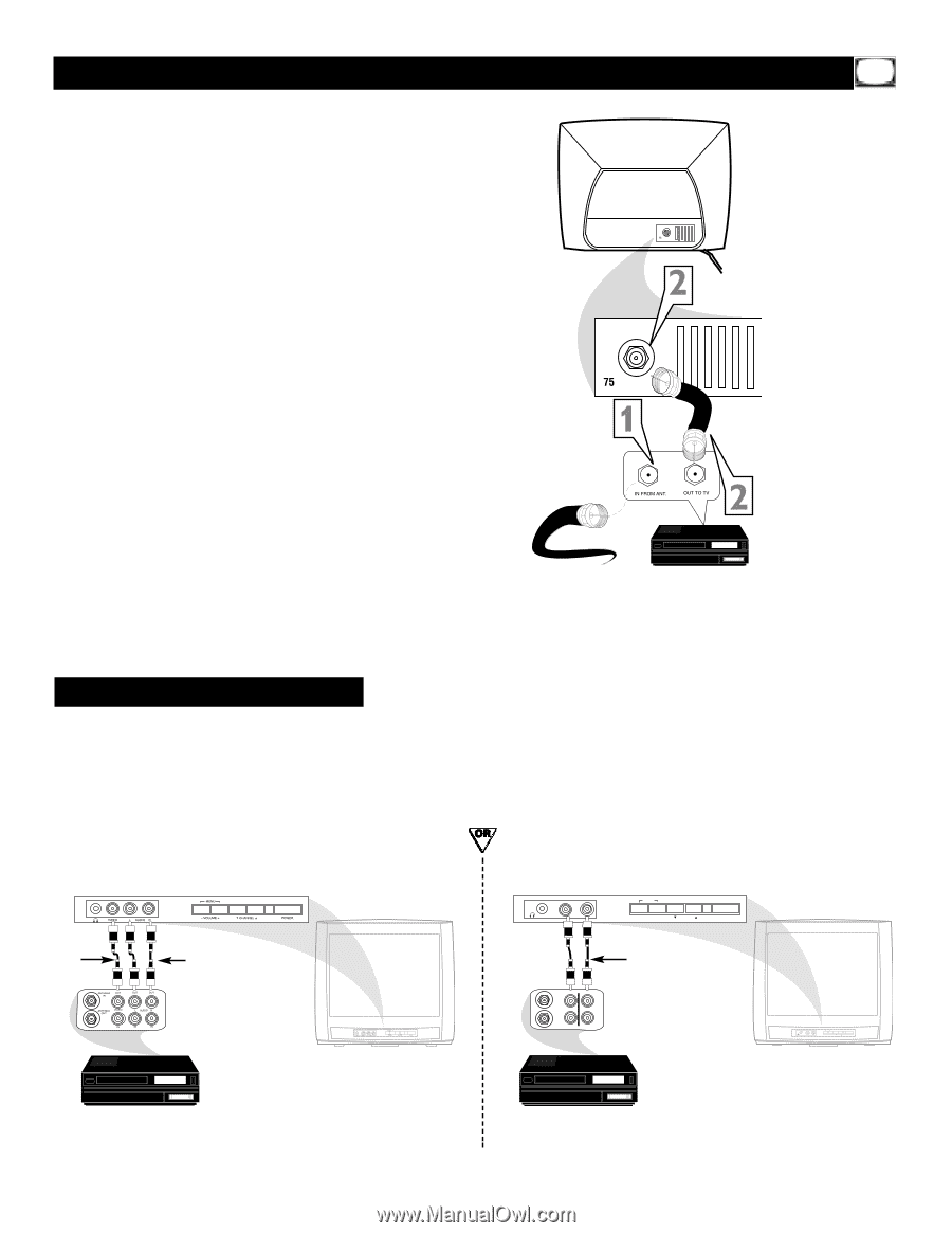
Basic TV to VCR (Accessory) Connection T he basic Antenna/Cable TV to Accessory (VCR, DVD Player, etc.) to TV connection is shown at right. For other hookups (such as those with Cable Boxes), refer to the owner's manual of the Cable Box or other Accessories. 1 Connect your Antenna or Cable TV signal to the IN (from Antenna or Antenna In) jack on the Accessory. 2 Use an RF coaxial cable to connect the OUT (to TV or Antenna Out) jack on the Accessory to the 75Ω jack on the TV. The necessary cables may be supplied with the Accessory, but are not supplied with the TV. 3 For VCR use, set the TV to channel 3 or 4 (same as the VCR's Channel 3/4 switch). To watch TV, change TV channels at the VCR. Or, turn off the VCR and change channels at the TV as usual. Ω Rear of TV Ω RF coaxial cable (75Ω) Cable TV signal or antenna VCR, etc. Audio/Video In jacks There are Audio and Video In jacks on the front of the TV. You can connect a Camcorder,VCR, or other accessory to these jacks, then watch the video from that equipment on the TV. Set the TV to the AV channel. (Go to your lowest TV channel, then change channels down to see the AV channel.) AUDIO/VIDEO IN jacks on front of Stereo TV (red and white AUDIO IN jacks) (20MS233S) Yellow Video cable Red and White Audio cables VCR, Camcorder, DVD Player, etc. with Audio and Video Out jacks AUDIO/VIDEO IN jacks on front of non-stereo TV (single white AUDIO IN jack) (13MT143S and 20MT133S) VIDEO AUDIO MENU - VOLUME + CHANNEL POWER ANTENNA IN OUT OUT ANTENNA VIDEO OUT AUDIO IN IN Yellow (video) and White (audio) cables VIDEO AUDIO MENU - VOLUME + CHANNEL POWER VCR, Camcorder, DVD Player, etc. with Audio and Video Out jacks 7
-
 1
1 -
 2
2 -
 3
3 -
 4
4 -
 5
5 -
 6
6 -
 7
7 -
 8
8 -
 9
9 -
 10
10 -
 11
11 -
 12
12 -
13
-
14
-
15
-
16
-
17
-
18
-
19
-
20
-
21
-
22
-
23
-
24
-
25
-
26
-
27
-
28
-
29
-
30
-
31
-
32
-
33
-
34
-
35
-
36
-
37
 |
 |