Magnavox 32MF339B User Manual - Page 5
Supplied Accessories, Attaching the Stand, Symbols Used in this Manual, Trademark Information - remote
 |
UPC - 609585163980
View all Magnavox 32MF339B manuals
Add to My Manuals
Save this manual to your list of manuals |
Page 5 highlights
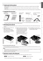
INTRODUCTION PREPARATION WATCHING TV OPTIONAL SETTING TROUBLESHOOTING INFORMATION Trademark Information • HDMI, the HDMI logo and High-Definition Multimedia Interface are trademarks or registered trademarks of HDMI Licensing LLC. • Manufactured under license from Dolby Laboratories. "Dolby" and the double-D symbol are trademarks of Dolby Laboratories. • Products that have earned ENERGY STAR® are designed to protect the environment through superior energy efficiency. Supplied Accessories user manual (1EMN24339B) quick start guide (1EMN24479) remote control (NF802UD) registration card (1EMN24699) screw kit for attaching the stand (1ESA19881) batteries (AAA x 2) AAA AAA [32MF369B only] High Speed HDMI cable (WPZ152TSN001 or WPZ152JVE001) • If you need to replace these accessories, please refer to the part No. with the illustrations and call our toll free customer support line found on the cover of this manual. Attaching the Stand You must attach the stand to the unit to have it as a table top unit. Be sure the front and rear of the stand match the proper direction. 1 2 3 Spread a thick and soft cloth over a Align the 2 stand hooks with the two Drive Phillips pan screws in the 4 table as shown below. hooks under the bottom of the main threaded holes at the bottom of the Place the main unit face down onto it. Make sure not to damage unit (shown by arrow ➀), then slide the stand in the direction as shown stand until they are tight. the screen. At least two people are by arrow ➁ until it stops and the 4 required at this step. mounting holes are aligned. Make sure not to put the AC power cord between the stand and the unit. ➂ screw holes ➁ ➀ front side ➀ To remove the stand from this unit Unscrew the Phillips pan screws indicated by above "➂" screw holes. After the screws are removed pull the stand up toward the rear of the unit. Be careful not to drop the stand when you remove it. Note: • When attaching the stand, ensure that all screws are tightly fastened. If the stand is not properly attached, it could cause the unit to fall, resulting in injuries as well as damage to the unit. • Make sure to use a table which can support the weight of this unit and is larger than this unit. • Make sure the table is in a stable location. Symbols Used in this Manual The following is the description for the symbols used in this manual. Description refers to: TV : Analog TV operation DTV : Digital TV operation • If neither symbol appears under the function heading, operation is applicable to both. 5 EN
-
 1
1 -
 2
2 -
 3
3 -
 4
4 -
 5
5 -
 6
6 -
 7
7 -
 8
8 -
 9
9 -
 10
10 -
 11
11 -
12
-
13
-
14
-
15
-
16
-
17
-
18
-
19
-
20
-
21
-
22
-
23
-
24
-
25
-
26
-
27
-
28
-
29
-
30
-
31
-
32
-
33
-
34
-
35
-
36
-
37
-
38
-
39
 |
 |
