Marantz SR7400 SR7400 User Guide - Page 16
Connecting Video Components
 |
View all Marantz SR7400 manuals
Add to My Manuals
Save this manual to your list of manuals |
Page 16 highlights
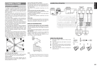
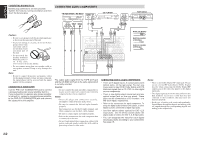
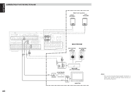
CONNECTING VIDEO COMPONENTS DVD PLAYER VIDEO PROJECTOR DIGITAL AUDIO VIDEO COMPONENT S-VIDEO OUT OUT OUT VIDEO OUT OUT Y CB / PB CR / PR LR COMPONENT S-VIDEO VIDEO IN IN Y CB / PB CR / PR LR ANTENNA COMPONENT VIDEO M INPUT-1 INPUT-2 MONITOR OUT Y CB/PB CR/PR Y CB/PB CR/PR Y CB/PB CR/PR FM (75Ω) GND AM VIDEO TV DVD VCR1 IN OUT DSS/VCR2 MONITOR MULTI IN OUT OUT OUT TV DVD VCR1 IN OUT S-VIDEO DSS/VCR2 MONITOR IN OUT OUT RS-232C MULTI RC-5 RC FLASHER IN L SL SBL C DIGITAL IN DIGITAL OUT IN 1 2 3 4 5 6 OPT. COAX. S PRE OUT TV DVD VCR1 DSS/VCR2 CD TAPE OUT CDR/MD DC OUT R MULTI L SR SL SBR SBL SW C L 7.1CH IN R IN OUT IN OUT IN OUT IN OUT OUT R SR SBR SW S AUDIO (AUX2) F F LR LR RL LR LR AUDIO AUDIO VIDEO OUT IN OUT IN L R LR S-VIDEO OUT IN VCR LR ENGLISH SATELLITE TUNER DIGITAL AUDIO VIDEO S-VIDEO OUT OUT OUT OUT LR LR LR ANTENNA COMPONENT VIDEO INPUT-1 Y CB/PB CR/PR INPUT-2 Y CB/PB CR/PR MONITOR OUT Y CB/PB CR/PR FM (75Ω) GND AM VIDEO TV DVD VCR1 IN OUT DSS/VCR2 MONITOR MULTI IN OUT OUT OUT TV DVD VCR1 IN OUT S-VIDEO DSS/VCR2 MONITOR IN OUT OUT RS-232C 1 TV L R DIGITAL IN 2 3 4 DVD VCR1 IN OUT MULTI RC-5 RC FLASHER IN L DIGITAL OUT IN 5 6 OPT. COAX. DSS/VCR2 CD TAPE OUT CDR/MD DC OUT R MULTI L SL SBL C PRE OUT SR SL SBR SBL SW C IN OUT 7.1CH IN IN OUT IN OUT OUT R SR SBR SW AUDIO (AUX2) RL LR AUDIO OUT LR VIDEO VIDEO S-VIDEO OUT IN IN VIDEO S-VIDEO ANALOG AUDIO DIGITAL AUDIO (COAXIAL) DIGITAL AUDIO (OPTICAL) TV VIDEO, S-VIDEO , COMPONENT JACKS There are 3 types of video jacks on the rear panel. VIDEO jack The video signal for the VIDEO jacks is the conventional composite video signal. S-VIDEO jack The video signal is separated into luminance (Y) and color (C) signals for the S-VIDEO jack. The SVIDEO signals enables high-quality color reproduction. If your video component has an SVIDEO output, we recommend to use it. Connect the S-VIDEO output jack on your video component to the S-VIDEO input jack on this unit. Component jack Make component video connections to a TV or monitor with component inputs to produce higher quality video images. Use a component video cable or 3 video cords to connect the component video out jacks on the SR7400 to the monitor. Notes: • Be sure to connect the left and right audio channels properly. Red connectors are for the R (right) channel, and white connectors are the for L (left) channel. • Be sure to connect the inputs and outputs of the video signals properly. • If you connect the S-VIDEO or component signal to the S-VIDEO or component jack on this unit, it is not necessary to connect the conventional video signal to the VIDEO (composite) jack. If you use both video inputs, this unit gives priority to the SVIDEO signal. • Each type of video jack works independently. Signals input to the VIDEO (composite) and SVIDEO jacks or component are output to the corresponding VIDEO (composite) and S-VIDEO or component jacks, respectively. • This unit has the "TV-AUTO ON/OFF" function to turn the TV ON or OFF automatically, by sensing the incoming video signal from the VIDEO jacks. • You may need to setup the digital audio output format of your DVD player, or other digital source components. Refer to the instructions of the each component connected to the digital input jacks. • There is no Dolby Digital RF input jack. Please use an external RF demodulator with a Dolby Digital decoder to connect a video disc player which has a Dolby Digital RF output jack to the digital input jack on this unit. 13
-
 1
1 -
2
-
3
-
4
-
5
-
6
-
7
-
8
-
9
-
10
-
 11
11 -
 12
12 -
 13
13 -
 14
14 -
 15
15 -
 16
16 -
 17
17 -
 18
18 -
 19
19 -
 20
20 -
 21
21 -
22
-
23
-
24
-
25
-
26
-
27
-
28
-
29
-
30
-
31
-
32
-
33
-
34
-
35
-
36
-
37
-
38
-
39
-
40
-
41
-
42
-
43
-
44
-
45
-
46
-
47
-
48
-
49
-
50
-
51
-
52
 |
 |
