Maytag MEW9530AS Installation Guide - Page 5
Electrical Requirements - oven
 |
View all Maytag MEW9530AS manuals
Add to My Manuals
Save this manual to your list of manuals |
Page 5 highlights
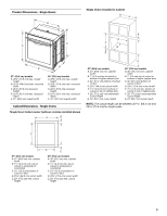
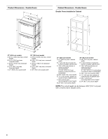
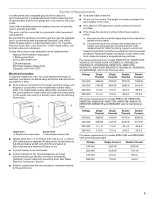
Electrical Requirements If codes permit and a separate ground wire is used, it is recommended that a qualified electrical installer determine that the ground path and the wire gauge are in accordance with local codes. Check with a qualified electrical installer if you are not sure the oven is properly grounded. This oven must be connected to a grounded metal, permanent wiring system. ■ Fuse both sides of the line. ■ Do not cut the conduit. The length of conduit provided is for serviceability of the oven. ■ A UL listed or CSA approved conduit connector must be provided. ■ If the house has aluminum wiring, follow the procedure below: Be sure that the electrical connection and wire size are adequate and in conformance with the National Electrical Code, ANSI/ NFPA 70-latest edition or CSA Standards C22.1-94, Canadian Electrical Code, Part 1 and C22.2 No. O-M91-latest edition, and all local codes and ordinances. 1. Connect a section of solid copper wire to the ends of the flexible conduit leads. 2. Connect the aluminum wiring to the added section of copper wire using special connectors and/or tools designed and UL listed for joining copper to aluminum. A copy of the above code standards can be obtained from: National Fire Protection Association 1 Batterymarch Park Quincy, MA 02169-7471 CSA International 8501 East Pleasant Valley Road Cleveland, OH 44131-5575 Follow the electrical connector manufacturer's recommended procedure. Aluminum/copper connection must conform with local codes and industry accepted wiring practices. For power requirements for models WOS51EC7A, WOS51EC0A, WOD51EC7A, WOD51EC0A, WOS92EC7A, WOS92EC0A, WOD93EC7A, WOD93EC0A, MEW7527A, MEW7530A, MEW7627A, MEW7630A, MEW9537A, MEW9627A, MEW9530A and MEW9630A, refer to the following table. Electrical Connection To properly install your oven, you must determine the type of electrical connection you will be using and follow the instructions provided for it here. Voltage 240 VAC Single Thermal 3690 W Single Convect 3720 W Double Thermal 7370 W Double Convect 7400 W ■ Oven must be connected to the proper electrical voltage and frequency as specified on the model/serial number rating plate. The model/serial number rating plate is located under the control panel on single ovens and under the control panel on the upper oven cavity on double ovens. See the following illustrations. A A 208 VAC 240 VAC 208 VAC 2790 W 15.4 A 13.4 A 2820 W 15.5 A 13.6 A 5580 W 30.7 A 26.8 A 5610 W 30.8 A 27.0 A For power requirements for models KEBK171B, KEBK101B, KEBK276B, KEBK206B, KEBS179B, KEBS109B, KEBS277B, KEBS279B, KEBS207B and KEBS209B, refer to the following table. Voltage Single Single Thermal Convect Double Double Thermal Convect 240 VAC 4090 W 4120 W 8170 W 8200 W 208 VAC 3099 W 3122 W 6190 W 6212 W 240 VAC 17.1 A 17.2 A 34.1 A 34.2 A Single Oven Double Oven A. Model/serial number plate A. Model/serial number plate ■ Models rated from 7.3 to 9 kW at 240 volts (5.4 to 7.4 kW at 208 volts) require a separate 40-amp circuit. Models rated at 4.8 kW and below at 240 volts (3.6 kW and below at 208 volts) require a separate 20-amp circuit. ■ A circuit breaker is recommended. ■ Connect directly to the circuit breaker box (or fused disconnect) through flexible, armored or nonmetallic sheathed, copper cable (with grounding wire). See "Make Electrical Connection" section. ■ Flexible conduit from the oven should be connected directly to the junction box. 208 VAC 14.9 A 15.0 A 29.8 A 29.9 A For power requirements for models KEBU109B and KEBU209B, refer to the following table. Voltage Single Convect Double Convect 240 VAC 5420 W 9500 W 208 VAC 4106 W 7197 W 240 VAC 22.6 A 39.6 A 208 VAC 19.8 A 34.6 A 5
-
 1
1 -
 2
2 -
 3
3 -
 4
4 -
 5
5 -
 6
6 -
 7
7 -
 8
8 -
 9
9 -
 10
10 -
 11
11 -
12
-
13
-
14
-
15
-
16
-
17
-
18
-
19
-
20
-
21
-
22
-
23
-
24
-
25
-
26
-
27
-
28
-
29
-
30
-
31
-
32
 |
 |
