Maytag MGDZ600TK Installation Instructions - Page 9
Venting
 |
UPC - 883049064994
View all Maytag MGDZ600TK manuals
Add to My Manuals
Save this manual to your list of manuals |
Page 9 highlights
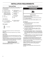
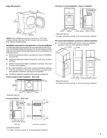
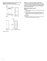
Dryer gas pipe ■ The gas pipe that comes out through the rear of your dryer has a 3/8" male pipe thread. 3. Open the shutoff valve in the supply line. The valve is open when the handle is parallel to the gas pipe. A B B *6¼" (159 mm) A 1½" (38 mm) A. 1/2" NPT gas supply line B. 3/8" NPT dryer pipe *NOTE: If the dryer is mounted on a pedestal, the gas pipe height must be an additional 10" (254 mm) or 15.5" (394 mm) from the floor, depending on the pedestal model. For a garage installation, the gas pipe height must be an additional 18" (460 mm) from the floor. Make Gas Connection 1. Remove the red cap from the gas pipe. 2. Using a wrench to tighten, connect the gas supply to the dryer. Use pipe-joint compound on the threads of all non-flared male fittings. If flexible metal tubing is used, be sure there are no kinks. A B A. Closed valve B. Open valve 4. Test all connections by brushing on an approved noncorrosive leak-detection solution. Bubbles will show a leak. Correct any leak found. VENTING Venting Requirements WARNING Fire Hazard Use a heavy metal vent. Do not use a plastic vent. Do not use a metal foil vent. Failure to follow these instructions can result in death or fire. A. Flared male fitting B. Non-flared male fitting NOTE: For LP gas connections, you must use pipe-joint compound resistant to the action of LP gas. Do not use TEFLON®† tape. A combination of pipe fittings must be used to connect the dryer to the existing gas line. Shown is a recommended connection. Your connection may be different, according to the supply line type, size and location. D WARNING: To reduce the risk of fire, this dryer MUST BE EXHAUSTED OUTDOORS. IMPORTANT: Observe all governing codes and ordinances. The dryer exhaust must not be connected into any gas vent, chimney, wall, ceiling, attic, crawlspace, or a concealed space of a building. Only rigid or flexible metal vent shall be used for exhausting. If using an existing vent system ■ Clean lint from the entire length of the system and make sure exhaust hood is not plugged with lint. ■ Replace any plastic or metal foil vent with rigid or flexible heavy metal vent. ■ Review vent system chart. Modify existing vent system if necessary to achieve the best drying performance. A B A. 3/8" flexible gas connector B. 3/8" dryer pipe C C. 3/8" to 3/8" pipe elbow D. 3/8" pipe-to-flare adapter fitting †®TEFLON is a registered trademark of E.I. Du Pont De Nemours and Company. 9
-
 1
1 -
2
-
3
-
 4
4 -
 5
5 -
 6
6 -
 7
7 -
 8
8 -
 9
9 -
 10
10 -
 11
11 -
 12
12 -
 13
13 -
 14
14 -
15
-
16
-
17
-
18
-
19
-
20
-
21
-
22
-
23
-
24
-
25
-
26
-
27
-
28
-
29
-
30
-
31
-
32
 |
 |
