Motorola 49901 Instruction Manual
Motorola 49901 - Vanguard 340 Router Manual
 |
UPC - 786523499018
View all Motorola 49901 manuals
Add to My Manuals
Save this manual to your list of manuals |
Motorola 49901 manual content summary:
- Motorola 49901 | Instruction Manual - Page 1
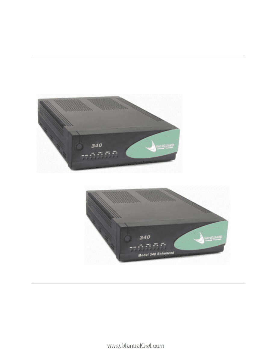
Vanguard Managed Solutions Vanguard 340 and 340 Enhanced Installation Manual - Motorola 49901 | Instruction Manual - Page 2
-4000 All rights reserved Printed in U.S.A. Restricted Rights Notification for U.S. Government Users The software (including firmware) addressed in this manual is provided to the U.S. Government under agreement which grants the government the minimum "restricted rights" in the software, as defined - Motorola 49901 | Instruction Manual - Page 3
. This equipment generates, uses, and can radiate radio frequency energy and, if not installed and used in accordance with the instruction manual, may cause harmful interference to radio communications. Changes or modifications not expressly approved by VanguardMS could void the user's authority to - Motorola 49901 | Instruction Manual - Page 4
the problem is resolved. Connection to party line service is subject to state tariffs. Contact the state public utility commission, public service commission Illustrator: Dennis Alves First Printing: February 2001 This manual is current for Release 6.4 of Vanguard Applications Ware To comment on this - Motorola 49901 | Instruction Manual - Page 5
Contents Special Notices and Translations Customer Information Customer Response Card Chapter 1. About the Vanguard 340 and 340 Enhanced Vanguard 340 and 340 Enhanced Descriptions 1-2 Features and Functionality 1-4 Target Applications 1-8 Virtual Private Network 1-9 Cost- - Motorola 49901 | Instruction Manual - Page 6
Contents (continued) Chapter 3. Installation and Replacement (Continued) Control Terminal Port (CTP 3-16 10/100BaseT Adapter Cable 3-17 DB25 V.24 Pinouts 3-18 DB25 V.35/V.36 Pinouts 3-19 DB25 X.21/V.11 Pinouts 3-20 Modifying Your Vanguard 340 and 340 Enhanced 3-22 Installing Vanguard - Motorola 49901 | Instruction Manual - Page 7
the Vanguard 340 and Vanguard 340 Enhanced. Note For information on operating system software and configuration, see the Vanguard Basic Configuration Manual (Part Number T0113). Audience This manual is intended for people who install and operate the Vanguard 340 and 340 Enhanced. How to Use This - Motorola 49901 | Instruction Manual - Page 8
) • Serial Feature Protocols (Part Number T0102) • Multi-Service Feature Protocols (Part Number T0103) • Multimedia Feature Protocols (Part Number T0104) • Alarms and Reports Manual (Part Number T0005) • Software Installation and Coldloading Manual (Part Number T0028) • IP and LAN Feature Protocols - Motorola 49901 | Instruction Manual - Page 9
About This Manual (continued) Vanguide CD-ROM The Vanguide CD-ROM contains all Vanguard documentation available at the time of release a VanguardMS Representative. VanguardMS Web Check the VanguardMS web site for the latest documentation: Site http://www.vanguardms.com/support/documentation/ ix - Motorola 49901 | Instruction Manual - Page 10
- Motorola 49901 | Instruction Manual - Page 11
Special Notices and Translations Special Notices The following notices emphasize certain information in the guide. Each serves a special purpose and is displayed in the format shown: Nota Note is used to emphasize any significant information. Advertencia Caution provides you with - Motorola 49901 | Instruction Manual - Page 12
ilmoitus ja se kertoo mahdollisesta loukkaantumisriskistä. French Messages spéciaux xii Les messages suivants mettent en valeur certaines informations dans le guide. Chacun d'eux remplit une fonction spéciale et est affiché dans le format indiqué : Important Important est utilisé pour souligner - Motorola 49901 | Instruction Manual - Page 13
darauf hin, daß ernsthafte Körperverletzungsgefahr besteht. I seguenti simboli, ciascuno con una speciale funzione, evidenziano determinate informazioni all'interno del manuale. Il formato è quello riportato qui di seguito. Nota Questo tipo di avvertimento viene utilizzato per evidenziare tutte le - Motorola 49901 | Instruction Manual - Page 14
Japanese Korean Norwegian Spesielle merknader Merknadstypene nedenfor representerer en bestemt type informasjon i håndboken. Hver merknadstype har en spesiell hensikt og vises på følgende format: Merk Merk brukes for å fremheve viktig informasjon. Forsiktig Forsiktig gir deg informasjon om - Motorola 49901 | Instruction Manual - Page 15
Portuguese/ Portugal Avisos Especiais Os avisos que se seguem realçam certas informações neste guia. Cada um deles serve um objectivo especial e é visualizado no formato apresentado: Nota Nota é utilizado para realçar qualquer informação importante. Atenção Atenção faculta-lhe informações que, se - Motorola 49901 | Instruction Manual - Page 16
Varning Varning är den mest allvarliga beteckningen och den indikerar att du kan skadas fysiskt. xvi - Motorola 49901 | Instruction Manual - Page 17
about Vanguard Managed Solutions products or services should contact your VanguardMS representative or visit this website for product, sales, support, documentation, or training information: http://www.vanguardms.com/ Comments About This Manual To help us improve our product documentation - Motorola 49901 | Instruction Manual - Page 18
- Motorola 49901 | Instruction Manual - Page 19
at the bottom of this page. Thank you for your help. Name Company Name Address Document Title: Vanguard 340 and 340 Enhanced Installation Manual Part Number: T0178 Revision G Please rate this document for usability: Excellent Good Average Below Average Poor What did you like about the - Motorola 49901 | Instruction Manual - Page 20
- Motorola 49901 | Instruction Manual - Page 21
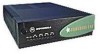
Overview Introduction Chapter 1 About the Vanguard 340 and 340 Enhanced This chapter describes the hardware and software functions, and the target applications for Vanguard 340 products. These topics are discussed: • Vanguard 340 and 340 Enhanced Descriptions • Features and Functionality • Target - Motorola 49901 | Instruction Manual - Page 22
to the Vanguard 340 Enhanced. The Vanguard 340 Enhanced (VG 340E) offers cost-effective integrated solutions that support: • Full voice and data IP Multi-service networking capabilities • Support for IP VPN's • Enhanced forwarding performance in throughput (for delivering converged IP voice and data - Motorola 49901 | Instruction Manual - Page 23
of LAN, SNA, and IP networking features. The Vanguard 340 and 340 Enhanced support two Vanguard Daughtercard slots for video, voice, fax and mixed protocol data traffic IP, Frame Relay, X.25, ISDN, or NX64 T1/E1 services. Note For descriptions of the daughtercards and other hardware components, refer - Motorola 49901 | Instruction Manual - Page 24
on your Vanguard, refer to the appropriate protocol document. These documents can be found on the VanguardMS Web site: http://www.vanguardms/support/documentation/ Vanguard 340 and The table below lists the different features for each product. 340 Enhanced Comparison Chart Product Name 340 LAN - Motorola 49901 | Instruction Manual - Page 25
Ethernet port with auto-sensing - Up to Six Voice Ports • ECC DIMM - Supports DES, Triple-DES (168-bit) AES. • External Power Supply 62749-03 (APS used as a Control Terminal Port (CTP) for configuration, reporting, and troubleshooting the Vanguard 340 and 340 Enhanced. To access the CTP you must - Motorola 49901 | Instruction Manual - Page 26
• ISDN BRI Voice • DSU • ECC DIM • V.90 • G.SHDSL Note Release 6.2 or greater software is required for the V.90. Release 6.3 and greater supports the enhanced ISDN BRI ST Data Daughtercard. Release 6.4 or greater software is required for the Vanguard 340 Enhanced. For additional information about - Motorola 49901 | Instruction Manual - Page 27
the SDRAM DIMM for operation. The Vanguard 340 and 340 Enhanced support the following Applications Ware packages: • IP+ Applications Ware Package ( Applications Ware Package (includes IP, and SNA) • Multi-Service Applications Ware Package. See the Software Release Notice accompanying your Vanguard - Motorola 49901 | Instruction Manual - Page 28
Target Applications Target Applications Introduction This section describes the various target applications for the Vanguard 340 and 340 Enhanced. These examples are shown are for the 340 and 340 Enhanced: • Virtual Private Network • IP and Serial Protocols over Frame Relay • Video and Serial - Motorola 49901 | Instruction Manual - Page 29
Encryption For detailed information about a VPN, refer to your Virtual Private Network Manual (VPN) (Part Number T0103-10). What is a VPN? A Virtual lines, WAN switches etcetera. The connectivity is provided by the service provider. - Operational Cost - Costs involved with maintaining leased lines - Motorola 49901 | Instruction Manual - Page 30
). Hardware Options Vanguard 340 Enhanced The Vanguard 340 Enhanced uses an ECC DIMM which supports DES, Triple-DES (168-bit) and AES Encryption. For detailed information regarding Encryption, refer to your Encryption Manual (Part Number T0103-09). 1-10 About the Vanguard 340 and 340 Enhanced - Motorola 49901 | Instruction Manual - Page 31
Remote Site Internet or IP Network Target Applications Central Site Remote Site Figure 1-1. Hardware-based VPN Solution for Site-to-Site Applications. About the Vanguard 340 and 340 Enhanced 1-11 - Motorola 49901 | Instruction Manual - Page 32
-site as well as remote access VPN implementations at layer 3 of the OSI model. Vanguard Applications Ware release 5.5 and greater supports these IPSec features: • Authentication Header (AH) and Encapsulating Security Payload (ESP) for user authentication and encryption. • Internet Key Exchange (IKE - Motorola 49901 | Instruction Manual - Page 33
Target Applications Frame Relay and X.25 Encryption Frame Relay and X.25 Networks Another value-added feature in Vanguard Managed Solutions VPN implementation is the ability to encrypt LAN traffic and serial legacy protocols (SNA, SDLC, SLAC, and TBOP) and tunnel them over Frame Relay and X.25 - Motorola 49901 | Instruction Manual - Page 34
Target Applications IP and Serial Protocols over Frame Relay Introduction The Vanguard 340 and 340 Enhanced support multi protocol encapsulation of IP traffic and serial protocols over frame relay as specified by RFC 1490. As shown in Figure 1-3, a SNA cluster controller connects - Motorola 49901 | Instruction Manual - Page 35
Video and Serial Protocols over Public or Private Networks Introduction As shown in Figure 1-4, the Vanguard 340 and 340 Enhanced can support encapsulation of video and serial protocols over public or private networks. This use of Vanguard 34x suits banking applications such as Automated - Motorola 49901 | Instruction Manual - Page 36
to central office connectivity over a public or private network as shown in Figure 1-5. The Vanguard 34x is equipped with a T1 daughtercard supports connectivity to the network at fractional T1 speeds. Security Monitoring Vanguard 34x Equipped with RemoteVU Daughtercards PC's Running Host Video - Motorola 49901 | Instruction Manual - Page 37
Branch and Central Office Security Monitoring at Branch Office Daughtercard Used Application Description DSU DIM, FXS/FXO and ISDN Daughtercards The Vanguard 34x supports voice, video and data traffic between the branch and central office over private or public network. The FXS/FXO Daughtercard - Motorola 49901 | Instruction Manual - Page 38
Target Applications SOHO and Branch Office to Central Office over ISDN Introduction The Vanguard 34x equipped with optional daughtercards provide a wide range of network solutions for companies with small branch offices or telecommuting employees working from a home office. A dial in or dedicated - Motorola 49901 | Instruction Manual - Page 39
Used Description FXS/FXO and ISDN Daughtercard Equipped with a Vanguard supporting the FXS/FXO and ISDN daughtercard, a work-at-home Internet from home. The Voice Over IP (VoIP) software feature provides voice support. FXS/FXO and ISDN Daughtercard Small branch offices can access the corporate - Motorola 49901 | Instruction Manual - Page 40
Target Applications Vanguard 340 and 340 Enhanced DSL and G.SHDSL DSL/Cable Modem The Vanguard 340, and 340 Enhanced support connectivity to high-speed broadband services such as DSL and Cable by connecting the 10/100BaseT port on the Vanguard 340 Enhanced to the Ethernet port on the DSL or Cable - Motorola 49901 | Instruction Manual - Page 41
340 Enhanced support connectivity to high-speed broadband services such as supported in either of the two daughtercard slots. For information on the G.SHDSL Daughtercard reference the G.SHDSL Manual (Part Number T0100-14). Installation instructions are available in the Daughtercard Installation Guide - Motorola 49901 | Instruction Manual - Page 42
Target Applications Clocking Limitations Clocking Limitations Vanguard 34x Listed below are the clocking issues relating to Port 3 of the Vanguard 34x: Vanguard 34x DCE INT --> VG6560/VG320/VG64xx EXT at 1.5 Mbps When a Vanguard 34x Port 3 is configured as internally clocked and is connected to a - Motorola 49901 | Instruction Manual - Page 43
Overview Introduction Chapter 2 Hardware Description This chapter describes the Vanguard 340 and 340 Enhanced: • Enclosuress • Motherboards • Vanguard Daughtercards Hardware Description 2-1 - Motorola 49901 | Instruction Manual - Page 44
Enclosures Enclosures Introduction This section describes the components of the enclosures. Vanguard 340 and 340 Enhanced Enclosure The Vanguard 340 and 340 Enhanced fit into a compact, low profile enclosure case that can be: • used as a desktop standalone device • seated on a shelf in a - Motorola 49901 | Instruction Manual - Page 45
unit. This serial number label is located on the rear panel of the Vanguard router. Refer to this serial number when contacting a Vanguard Managed Solutions Service Representative. Hardware Description 2-3 - Motorola 49901 | Instruction Manual - Page 46
Motherboards Motherboards General Description Vanguard 340 Motherboard The Vanguard 340 and 340 Enhanced motherboards contain different components. Figure 2-3 and Figure 2-4 show the two motherboards. The Vanguard 340 motherboard contains 4 Megabytes of Non-Volatile FLASH on board and has 16 - Motorola 49901 | Instruction Manual - Page 47
Motherboards Figure 2-3 shows the location of the motherboard components of the Vanguard 340. Battery SDRAM DIMM Slot Data Compression/ Encryption SIMM Slot Flash SIMM Slot 2 Daughtercard Slots Fan Connector Vanguard 340 Enhanced Motherboard Power Supply Connector DB25 (DCE) Control Terminal - Motorola 49901 | Instruction Manual - Page 48
Motherboards • A battery that provides power for the unit's real time clock • 10/100BaseT Ethernet (RJ-45connector) • Control Terminal Port (RJ-45connector) • DB-25 Connector Figure 2-4 shows the location of the 340 Enhanced motherboard components. AES Encryption ECC DIMM Slot SDRAM Slot Vanguard - Motorola 49901 | Instruction Manual - Page 49
card would go in port 2. For more information refer to Chapter Five of the Daughtercard Installation Guide (Part Number T0020). Serial Interface The Vanguard 340 and 340 Enhanced support a serial interface that is installed on the motherboard. The serial interface can be configured to function - Motorola 49901 | Instruction Manual - Page 50
FLASH SIMM Device Part Number (PN) can be found in small print on the face of the SIMM device. For further assistance, please call VanguardMS Service. 2-8 Hardware Description - Motorola 49901 | Instruction Manual - Page 51
ISDN BRI-S/T Voice • DSU • DIM • V.34 • V.90 • G.SHDSL Vanguard 340 Enhanced supports: • 1-Port FXS/FXO Voice • 2-Port Voice FXS • 4-Port Voice FXS • 4-Port Voice these cards. For instructions for installing these cards, refer to the Vanguard Daughtercard Installation Guide (Part Number T0020). - Motorola 49901 | Instruction Manual - Page 52
each. The 2-Port Voice FXS Daughtercard has two RJ11 connectors for two FXS Ports. The two ports can be used simultaneously and each port supports one voice channel. Figure 2-7 shows the 2 Port Voice FXS Daughtercard connectors as they appear on the back panel. 12 LOC REM FXS-1 FXS-2 Figure - Motorola 49901 | Instruction Manual - Page 53
or FXS or 1 Single FXO or FXS The FT1/FE1 Daughtercards allow the Vanguard 34x to transfer data over a T1 or E1 network. The daughtercards support these full and fractional T1 or E1 speeds: • The FE1 Daughtercard provides line rates 2.048 Mbps and data rates of n x 64 kbps (where n is 1 to - Motorola 49901 | Instruction Manual - Page 54
should refer to the Vanguard Daughtercard Installation Guide. The purpose is to point out that ACA TS-016-1997 for connection to E1 SELV services. The E1 interface meets the IEC 60950 specifications for and transports the data. In addition to supporting live video streams, the daughtercard has a - Motorola 49901 | Instruction Manual - Page 55
Euro Numeric switch types • D Channel Packet Mode • Leased Circuit Services (I Interface) • Permanent B for German Monopol support or Japan High-Speed Digital Figure 2-14 shows the ISDN BRI Vanguard Integrated Services Digital Network: ISDN Manual (Part Number T0103-06). Hardware Description 2-13 - Motorola 49901 | Instruction Manual - Page 56
ECMA 143 - QSIG Basic Service to connect to PBXs over private line. • ECMA 165 - QSIG Generic Functions for Support of PBX Supplementary Services. • ITU-T G.711A For more information on supported daughtercard configurations, refer to the Daughtercard Installation Manual (Part Number T0020) Chapter - Motorola 49901 | Instruction Manual - Page 57
Vanguard Daughtercards DIM V.34 Modem This card supports a single V.11, V.24, V.35, or V.36 DIM (Digital the rear panel connectors on the V.90 modem daughtercard. For installation instructions, refer to the Vanguard Daughtercard Installation Guide (Part Number T0020). Line MR CD .RI OH RXD RJ - Motorola 49901 | Instruction Manual - Page 58
supported in either of the two daughtercard slots. Figure 2-20 shows the rear panel connector on the G.SHDSL Daughtercard. For information on the G.SHDSL Daughtercard reference the G.SHDSL Manual (Part Number T0100-14). Installation instructions are available in the Daughtercard Installation Guide - Motorola 49901 | Instruction Manual - Page 59
Chapter 3 Installation and Replacement This chapter describes how to install, cable, and modify your Vanguard 340 and 340 Enhanced device. Instructions are provided for the following tasks: • Checking Your Shipment Contents • Installing the Vanguard 340 and 340 Enhanced • Configuring the Serial - Motorola 49901 | Instruction Manual - Page 60
Checking Your Shipment Contents Checking Your Shipment Contents List of Contents The Vanguard 340 and 340 Enhanced are packaged in shock-absorbent packing material. Inside your shipping carton, you should find the contents shown in Figure 3-1. Before installing the Vanguard hardware, make sure - Motorola 49901 | Instruction Manual - Page 61
340 Enhanced After your Vanguard 34x is installed and cabled, go to the "Powering Up Your Vanguard 340 and 340 Enhanced" section in Chapter 4 for instructions on poweringup the unit. Installation and Replacement 3-3 - Motorola 49901 | Instruction Manual - Page 62
equipment. Contact your telephone company or an electronic accessories vendor for information on lightning protection equipment. If you experience problems caused by surges from lightning, install appropriately rated surge suppressors on power and data lines connected to your Vanguard. Mise - Motorola 49901 | Instruction Manual - Page 63
Installing the Vanguard 340 and 340 Enhanced Mise en Garde Afin d'éviter toute surchauffe des circuits de l'unité, ne placez aucun objet sur l'unité à moins de 2,5 cm (1 pouce) des conduits de ventilation du panneau avant et à moins de 30,5 cm (12 pouces) de l'arrière de l'unité. Vorsicht Zur - Motorola 49901 | Instruction Manual - Page 64
Installing the Vanguard 340 and 340 Enhanced Installing Your Vanguard 340 and 340 Enhanced Installation Complete these steps to install your Vanguard 340 and 340 Enhanced: Step Action 1 Unpack the Vanguard 34x, and inspect the unit to ensure you have all the components. 2 Install any - Motorola 49901 | Instruction Manual - Page 65
Installing the Vanguard 340 and 340 Enhanced Thermal Considerations Introduction This section explains some of the heat and temperature factors that can affect your Vanguard 34x. Fan After the Vanguard 340 is installed, power it up and check that the fan is working properly. The feet must be - Motorola 49901 | Instruction Manual - Page 66
information on DTE capability, refer to the "Setting the Interface Options" section on page 3-10. The Serial Interface The serial interface is supported in the Port Configuration menu and can be Parameters configured using the Control Terminal Port (CTP). Included in the Port Configuration menu - Motorola 49901 | Instruction Manual - Page 67
Configuring the Serial Interface Setting the Interface Type Introduction This section provides instructions for setting the Interface Type parameter. Interface Type Parameter Use this procedure to set the Interface Type parameter: Step 1 2 3 4 5 Action From the Control Terminal Port - Motorola 49901 | Instruction Manual - Page 68
Configuring the Serial Interface Setting the Interface Options Introduction This section provides instruction for setting the Interface Options parameter. V.24 Interface Type Use this procedure to set the Interface Options parameter for V.24 interface type: Step Action Result/ - Motorola 49901 | Instruction Manual - Page 69
Configuring the Serial Interface V.35/V.36, and X.21/ Use this procedure to set the Interface Options parameter for V.35, V.36, and V.11 Interface X.21/V.11 interface types: Types Step Action Result/Description 1 From the Control Terminal The Port record appears. Port Main menu, select - Motorola 49901 | Instruction Manual - Page 70
Cabling the Vanguard 340 and 340 Enhanced Cabling the Vanguard 340 and 340 Enhanced Introduction This section provides information to help you cable your Vanguard 340 and 340 Enhanced. Caution Before connecting cables to the motherboard or daughtercard ports, be sure that the screws holding the - Motorola 49901 | Instruction Manual - Page 71
Cabling the Vanguard 340 and 340 Enhanced Port Characteristics and Cabling Introduction This section describes the port characteristics and cables required to connect to the Vanguard 340 and 340 Enhanced. Port This table lists the port characteristics, connector and cable requirements: - Motorola 49901 | Instruction Manual - Page 72
Cabling the Vanguard 340 and 340 Enhanced Port Connector (conti Interface Cable Required (Application Specific) Speed 1 BNC Pair (cont.) FE1 Daughtercard 2 BNC-to-BNC 75ohm Full or fractional E1 Coax Cable speeds RJ45 Dual E&M RJ45-to-RJ45 Cable N/A Daughtercard RJ11 V.34 & V.90 - Motorola 49901 | Instruction Manual - Page 73
10/100BaseT Adapter cable 100Mbps or standard UTP cable (RJ45-to-RJ45) *Enhanced ISDN BRI ST Data information refer to the Daughtercard Guide (Part Number T0020). Port Numbering for Daughtercards installed in ports 1 and 2 must be configured correctly. For example, Physical Ports 1 if you have - Motorola 49901 | Instruction Manual - Page 74
Cabling the Vanguard 340 and 340 Enhanced Control Terminal Port (CTP) Port 4 Connector Pinout Use the supplied RJ45/DB25 cable to connect to the CTP Port and perform CTP operations such as coldloading software images into a Vanguard 34x. The Vanguard 34x defaults this port to 9.6 kbps, 8 bits, no - Motorola 49901 | Instruction Manual - Page 75
Cabling the Vanguard 340 and 340 Enhanced 10/100BaseT Adapter Cable Specifications The 10/100BaseT cable has the following specifications: • Cable Type: Category 5 or better • Connectors: RJ45 to RJ45 • Color: Gray • Part Number: 61798-01 Port 5 Connector Pinout The 10/100BaseT Ethernet Port - Motorola 49901 | Instruction Manual - Page 76
Cabling the Vanguard 340 and 340 Enhanced DB25 V.24 Pinouts Connector Pinouts This table shows the DB25 V.24 connector pinouts for DCE/DTE mode. To use DTE to DTE or DCE to DCE mode, a crossover adapter cable is required. Refer to Figure 3-5 on page 3-21 for crossover cable connections. These pins - Motorola 49901 | Instruction Manual - Page 77
Cabling the Vanguard 340 and 340 Enhanced DB25 V.35/V.36 Pinouts Connector Pinout This table shows the DB25 V.35/V.36 connector pinouts for DCE/DTE mode. To use DTE to DTE or DCE to DCE mode, a crossover adapter cable is required. Refer to Figure 3-5 on page 3-21 for crossover cable connections: - Motorola 49901 | Instruction Manual - Page 78
Cabling the Vanguard 340 and 340 Enhanced DB25 X.21/V.11 Pinouts Connector Pinout This table shows the DB25 X.21/V.11 connector pinouts for DCE/DTE mode. To use DTE to DTE or DCE to DCE mode, a crossover adapter cable is required. Refer to Figure 3-5 on page 3-21 for crossover cable connections: - Motorola 49901 | Instruction Manual - Page 79
Cabling the Vanguard 340 and 340 Enhanced Crossover Cable The diagram in Figure 3-5 shows the crossover cable connections for DCE to DCE Connections mode. DCE 2 3 4 8 6 20 17 24 DCE 2 3 4 8 6 20 17 24 Figure 3-5. Crossover Cable Connections Ordering Cables To order cables please contact a - Motorola 49901 | Instruction Manual - Page 80
Modifying Your Vanguard 340 and 340 Enhanced Modifying Your Vanguard 340 and 340 Enhanced Introduction You can modify your Vanguard 34x by adding or replacing components on the motherboard. This section explains how to make these modifications and includes the following topics: • Installing - Motorola 49901 | Instruction Manual - Page 81
factory or on-site. Refer to the Vanguard Daughtercard Installation Guide (Part Number T0020) for complete daughtercard installation instructions. Caution On-site installation of these daughtercards should be undertaken by trained service technicians. Mise en Garde L'installation de ces cartes fille - Motorola 49901 | Instruction Manual - Page 82
Modifying Your Vanguard 340 and 340 Enhanced Accessing the Motherboard Introduction This section explains how to access the motherboard for the Vanguard 340 and 340 Enhanced. It also identifies the location of the key motherboard components. Before replacing SIMMs, DIMM, batteries, or - Motorola 49901 | Instruction Manual - Page 83
Modifying Your Vanguard 340 and 340 Enhanced Vorsicht Einige im 340 verwendeten Komponenten sollten keinen elektrostatischen Entladungen ausgesetzt werden, durch die interne Bauteile beschädigt werden können. Wenden Sie die entsprechenden Maßnahmen zur Erdung und zum Schutz vor statischen Ladungen - Motorola 49901 | Instruction Manual - Page 84
flat surface. Use the steps to install the Vanguard 340 and 340 Enhanced motherboard: Step 1 2 3 4 Action Carefully slide the motherboard into the card guides within the opening. Push the motherboard into the enclosure. Tighten the screws on both sides of the chassis. Be sure the screws are snug - Motorola 49901 | Instruction Manual - Page 85
section explains how to add and remove the: • SDRAM DIMM • FLASH SIMM • Data Compression/Encryption SIMM (340) • ECC DIMM (340 Enhanced) For instructions on removing the motherboard, refer to the "Accessing the Motherboard" section on page 3-24. Caution Be careful when installing a Data Compression - Motorola 49901 | Instruction Manual - Page 86
Modifying Your Vanguard 340 and 340 Enhanced Note The location of the FLASH SIMM and Data Compression (DCC/DSP)/ Encryption SIMM are indicated on the motherboard as shown in Figure 3-8. Adding/Removing SDRAM DIMM Use these steps to add and remove a SDRAM DIMM: 1) Insert the DIMM into slot U173 as - Motorola 49901 | Instruction Manual - Page 87
Data Compression/ Encryption SIMM Modifying Your Vanguard 340 and 340 Enhanced SDRAM DIMM Locking levers Locking tabs FLASH SIMM Figure 3-7. SIMM and DIMM Installation/Replacement Installation and Replacement 3-29 - Motorola 49901 | Instruction Manual - Page 88
Modifying Your Vanguard 340 and 340 Enhanced Battery SDRAM DIMM Slot 2 Daughtercard Slots Data Compression/ Encryption SIMM Slot Flash SIMM Slot Fan Connector Power Supply Connector DB25 (DCE) Control Terminal Port (CTP) 10/100 BaseT Ethernet Port Figure 3-8. Location of Vanguard 340 - Motorola 49901 | Instruction Manual - Page 89
Modifying Your Vanguard 340 and 340 Enhanced Vanguard 340 Enhanced ECC DIMM Installation Figure 3-8 shows the locations of the SIMM and DIMM slots: • SDRAM DIMM • FLASH SIMM • ECC DIMM Use these steps to add and remove an ECC DIMM: 1) At a slight angle, insert the SIMM into the connector, lining up - Motorola 49901 | Instruction Manual - Page 90
Modifying Your Vanguard 340 and 340 Enhanced AES Encryption ECC DIMM Slot SDRAM Slot Vanguard Daughtercard Slots Battery FLASH SIMM Slot Power Supply Connector DB25 (DCE) Control Terminal Port (CTP) Figure 3-9. ECC DIMM Installation 10/100 BaseT Ethernet Port 3-32 Installation and - Motorola 49901 | Instruction Manual - Page 91
is not used to store the configuration memory. Warning Only qualified service personnel should perform the procedure described in this section. If the battery The lithium battery should be replaced every six years. Follow the instructions in Figure 3-10 to replace the battery. Before Removing/ - Motorola 49901 | Instruction Manual - Page 92
Modifying Your Vanguard 340 and 340 Enhanced Removing/ Installing the Battery Figure 3-10 shows how to install and replace the battery. To remove the battery Using your fingers, push the retaining tabs aside and pry the battery out of the holder. To install the battery Place the battery in the - Motorola 49901 | Instruction Manual - Page 93
Overview Introduction Chapter 4 Powering Up and Loading Software This chapter describes: • Powering Up Your Vanguard 340 and 340 Enhanced • Powering Off The Vanguard 340 and 340 Enhanced • Powerup Diagnostics • Accessing the Control Terminal Port • Obtaining and Installing Operating Software - Motorola 49901 | Instruction Manual - Page 94
Powering Up Your Vanguard 340 and 340 Enhanced Powering Up Your Vanguard 340 and 340 Enhanced Introduction This section describes the sequence of events when you power up and power down the Vanguard 34x. Powering On the Vanguard 34x The Vanguard 34x does not have a power switch on the unit. Use - Motorola 49901 | Instruction Manual - Page 95
Powering Off The Vanguard 340 and 340 Enhanced Powering Off The Vanguard 340 and 340 Enhanced Warning When powering down the unit, always unplug the power cord from the AC power outlet first (Figure 4-1). Never disconnect or reconnect the power connector from the Vanguard back panel if the power - Motorola 49901 | Instruction Manual - Page 96
Powering Off The Vanguard 340 and 340 Enhanced Warning Hazardous voltage from the telecommunications network may be accessible on un-earthed units. Disconnect all telecommunications cables before removing the main lead from the power supply. Des tensions dangereuses provenant des réseaux de télé - Motorola 49901 | Instruction Manual - Page 97
Powerup Diagnostics Powerup Diagnostics Introduction Detailed Front Panel LEDs This section describes diagnostics that run automatically when you power up the Vanguard 340 and 340 Enhanced. Figure 4-3 illustrates the detailed front panel LEDs located behind the front cover. Reset Resets (restarts - Motorola 49901 | Instruction Manual - Page 98
the following when ON or OFF: • ON - Alarm condition data path is disrupted, refer to the FT1/FE1 interface statistics for more information on the problem. • OFF - Normal operation exists. - Motorola 49901 | Instruction Manual - Page 99
does not provide all information about accessing the CTP. For more information on accessing and using the CTP refer to the Vanguard Basic Configuration Manual (Part Number T0113). Follow these steps to access the Vanguard 34x CTP Main menu: Note This procedure assumes that a PC or terminal is - Motorola 49901 | Instruction Manual - Page 100
Accessing the Control Terminal Port Alternative Methods for Accessing the CTP Introduction This section describes alternative methods for accessing the CTP over a Frame Relay Bypass connection when: • the terminal of the local Vanguard device does not have IP connectivity or • cannot connect to - Motorola 49901 | Instruction Manual - Page 101
the Applications Ware package contact your distributor, VanguardMS sales or service. Operating Software The operating software is compressed in FLASH and operating software, refer to the Vanguard Software Installation and Coldloading Manual (Part Number T0028) included on the CD-ROM. Optional - Motorola 49901 | Instruction Manual - Page 102
Obtaining and Installing Operating Software Operating Software Operating software files located on the Vanguide CD-ROM, and on the World Wide File Formats Web, adhere to the following file naming formats: Filename: XXp01.xrc Description where: • XX identifies the software release number - Motorola 49901 | Instruction Manual - Page 103
Appendix A Specifications Specifications Introduction 340 Hardware 340 Enhanced Hardware This section describes the physical and environmental specifications and power requirements for the Vanguard 340 and 340 Enhanced products. The Vanguard 340 product features the following: • 50 Mhz MPC860T - Motorola 49901 | Instruction Manual - Page 104
Software Environmental The Vanguard 340 and 340 Enhanced support these software applications ware: • IP+ Package • SNA+ Package • Multi-Service Package See the Software Release Notice accompanying your Vanguard unit for more information on the software license upgrades available for the Vanguard - Motorola 49901 | Instruction Manual - Page 105
Electromagnetic Compatibility Power Requirements Power Supply Description Safety Physical Vanguard 340 and 340 Enhanced products adhere to the following: • FCC Part 15, Class A • CISPR 22 and EN 55022, Class A • AS 3548, Class A • EN 50082-1 Vanguard 340 power requirements: • 100 to 240 VAC nominal - Motorola 49901 | Instruction Manual - Page 106
- Motorola 49901 | Instruction Manual - Page 107
Overview Introduction Appendix B Software License and Regulatory Information This appendix provides information about the following: • FCC Part 68 and Telephone Company Procedures and Requirements • Product Declarations and Regulatory Information Software License and Regulatory Information B-1 - Motorola 49901 | Instruction Manual - Page 108
-BN 04DU9-2SN ---------- Troubleshooting Your Connection If any of your equipment is not operating correctly, immediately remove it from the telephone line before damaging the network. If the telephone company is aware of the problem, they may temporarily disconnect your service. Whenever possible - Motorola 49901 | Instruction Manual - Page 109
FCC regulations and telephone company procedures prohibit connection of Telephone customer-provided equipment to telephone company-provided coin service Equipment (central office-implemented systems). Connection to party lines is subject to state tariffs. Occasionally, the telephone company - Motorola 49901 | Instruction Manual - Page 110
, safety statements, and ISDN Type Approvals. Warnings And Cautions The following special notices apply to all equipment handling procedures in this installation guide. Warning Ports capable of connecting to ports on other apparatus are defined as Safety Extra Low Voltage (SELV). To conform with - Motorola 49901 | Instruction Manual - Page 111
Product Declarations and Regulatory Information Declarations of Conformity English Declaration of Conformity: Hereby, VanguardMS declares that this Vanguard Router is in compliance with the requirement and other relevant provisions of Directive 1999/5/EC. Danish K o n fo rm itetserk læ rin g : H e - Motorola 49901 | Instruction Manual - Page 112
Product Declarations and Regulatory Information Italian Dichiarazione di conformità: Con la presente VanguardMS dichiara che il router Vanguard soddisfa i requisiti essenziali e le altre disposizioni pertinenti della direttiva 1999/5/CE. Portuguese Declaração de Conformidade: Através da presente, a - Motorola 49901 | Instruction Manual - Page 113
also be installed using an acceptable method of connection. In some cases, the company's inside wiring associated with a single line individual service might be extended by means of a certified connector assembly (telephone extension cord). The customer should be aware that compliance with the above - Motorola 49901 | Instruction Manual - Page 114
- Motorola 49901 | Instruction Manual - Page 115
the Product will conform to its then-current published specifications and will be free from defects in materials and workmanship under normal use and service for a period of (ONE) 1 YEAR from the date of purchase by the original end user. During the warranty period, Vanguard Managed Solutions will - Motorola 49901 | Instruction Manual - Page 116
- Motorola 49901 | Instruction Manual - Page 117
equipment return procedures, on-site service or unit Procedures exchange service call the VanguardMS Technical Support Center at (800) 544-0062 Customer Operations Center at (800) 544-0062 for return authorization and instructions. You will be asked to provide the following information: • Product - Motorola 49901 | Instruction Manual - Page 118
VanguardMS Technical Support Center at (800) 544-0062, for return authorization and instructions. When you call, you will be given a Return Material Authorization (RMA) control number. Mark this number clearly on the shipping container for ease of identification and faster service - Motorola 49901 | Instruction Manual - Page 119
Numerics 1 Port Voice FXS/FXO Daughtercard 2-10 10/100BaseT Ethernet cable 1-5 2 Port Voice FXS Daughtercard 2-10, 2-11 4 Port Voice FXO Daughtercard 2-11 4 Port Voice FXS Daughtercard 2-11 56 K DSU/CSU Daughtercard 2-14 A Accessing the Control Terminal Port (CTP) 4-7 Accessing the Motherboard 2-7 - Motorola 49901 | Instruction Manual - Page 120
I Installation Instructions 3-6 Interface Type V.24 3-10 V.35/V.36 3-11 X.21/V.11 3-11 ISDN BRI-S/T operating software file formats 4-10 Ordering Connections facility interface code B-2 interface type B-2 service code B-2 USOC jack connector B-2 Ordering information CD-ROM products viiix P Physical - Motorola 49901 | Instruction Manual - Page 121
T Telephone Company Procedures B-2 Temperature 3-7 Thermal Considerations 3-7 Thermal Shutdown 3-7 Troubleshooting connections B-2 V V.34 Modem Daughtercard 2-15 Vanguard 34x cabling rear panel 3-12 configuration 3-12 description 1-2 enclosure 2-2 features 1-4 front panel 2-2 installation 3-6
-
 1
1 -
 2
2 -
 3
3 -
 4
4 -
 5
5 -
 6
6 -
 7
7 -
8
-
9
-
10
-
11
-
12
-
13
-
14
-
15
-
16
-
17
-
18
-
19
-
20
-
21
-
22
-
23
-
24
-
25
-
26
-
27
-
28
-
29
-
30
-
31
-
32
-
33
-
34
-
35
-
36
-
37
-
38
-
39
-
40
-
41
-
42
-
43
-
44
-
45
-
46
-
47
-
48
-
49
-
50
-
51
-
52
-
53
-
54
-
55
-
56
-
57
-
58
-
59
-
60
-
61
-
62
-
63
-
64
-
65
-
66
-
67
-
68
-
69
-
70
-
71
-
72
-
73
-
74
-
75
-
76
-
77
-
78
-
79
-
80
-
81
-
82
-
83
-
84
-
85
-
86
-
87
-
88
-
89
-
90
-
91
-
92
-
93
-
94
-
95
-
96
-
97
-
98
-
99
-
100
-
101
-
102
-
103
-
104
-
105
-
106
-
107
-
108
-
109
-
110
-
111
-
112
-
113
-
114
-
115
-
116
-
117
-
118
-
119
-
120
-
121
 |
 |
Vanguard Managed Solutions
Vanguard 340 and 340 Enhanced
Installation Manual