Netgear GSM7324 FSM7326P Hardware manual - Page 12
GSM7312 Rear Panel, Table 2-2. GSM7312 LED Description continued
 |
UPC - 606449029062
View all Netgear GSM7324 manuals
Add to My Manuals
Save this manual to your list of manuals |
Page 12 highlights
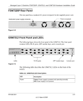
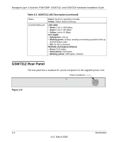
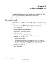
Managed Layer 3 Switches FSM7326P, GSM7312, and GSM7324 Hardware Installation Guide Table 2-2. GSM7312 LED Description (continued) Status 10/100/1000M port Green: Switch is operating normally. Yellow: Switch failed to boot up. LINK (left) • Green: Link in 1000 Mbps. • Green: Link in 100 Mbps. • Yellow: Link in 10 Mbps. ACT (right) • Solid green: Link up. • Blinking green: Activity, sending or receiving a packet in link up and full-duplex state. • Off: No link is detected. FDX/COL (full duplex/collision) • Green: Full duplex. • Solid yellow: Half duplex. • Blinking yellow: Half duplex, collision. GSM7312 Rear Panel The rear panel has a standard AC power receptacle for the supplied power cord. Power receptacle Figure 2-4 2-4 Introduction v1.0, March 2006
-
 1
1 -
2
-
3
-
4
-
5
-
6
-
 7
7 -
 8
8 -
 9
9 -
 10
10 -
 11
11 -
 12
12 -
 13
13 -
 14
14 -
 15
15 -
 16
16 -
 17
17 -
18
-
19
-
20
-
21
-
22
-
23
-
24
-
25
-
26
-
27
-
28
-
29
-
30
-
31
-
32
-
33
-
34
-
35
-
36
-
37
-
38
 |
 |
