Netgear WC7600 Installation Guide - Page 3
Meet Your Wireless Controller
 |
View all Netgear WC7600 manuals
Add to My Manuals
Save this manual to your list of manuals |
Page 3 highlights
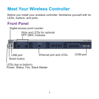
Meet Your Wireless Controller Before you install your wireless controller, familiarize yourself with its LEDs, buttons, and ports. Front Panel Digital access point counter Slots and LEDs for optional SFP GBIC modules ID Power Status Fan Stack Master USB Reset LED Mode: Green= Link at 10G, Blink Green=10G Active, Yellow=Link at 1G, Blink Yellow=1G Active LED Mode: Left LED: Green=Link at 1G E, Yellow=Link at 10/100M Right LED:Green=Link, Green Blink=Active USB port Reset button Ethernet port and LEDs LEDs (top to bottom): Power, Status, Fan, Stack Master Console 9600,N,8,1 COM port 3
-
 1
1 -
 2
2 -
 3
3 -
 4
4 -
 5
5 -
 6
6 -
 7
7 -
 8
8 -
 9
9 -
10
-
11
-
12
-
13
-
14
-
15
-
16
 |
 |

3
Meet Your Wireless Controller
Before you install your wireless controller, familiarize yourself with its
LEDs, buttons, and ports.
Front Panel
Console 9600,N,8,1
LED Mode:
Left LED: Green=Link at 1G E,
Yellow=Link at 10/100M
Right LED:Green=Link,
Green Blink=Active
LED Mode:
Green= Link at 10G, Blink Green=10G Active,
Yellow=Link at 1G, Blink Yellow=1G Active
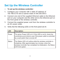
Power
Status
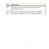
Fan
Stack
Master
Reset
USB
ID
LEDs (top to bottom):
Power, Status, Fan, Stack Master
Reset button
USB port
Digital access point counter
Slots and LEDs for optional
Ethernet port and LEDs
SFP GBIC modules
COM port