NordicTrack E 3700 Treadmill Uk Manual - Page 6
Assembly
 |
View all NordicTrack E 3700 Treadmill manuals
Add to My Manuals
Save this manual to your list of manuals |
Page 6 highlights
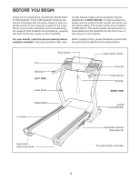
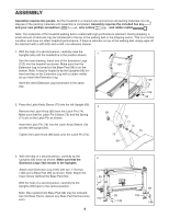
ASSEMBLY Assembly requires two people. Set the treadmill in a cleared area and remove all packing materials. Do not dispose of the packing materials until assembly is completed. Assembly requires the included hex key and your own phillips screwdriver , wire cutters , and rubber mallet . Note: The underside of the treadmill walking belt is coated with high-performance lubricant. During shipping, a small amount of lubricant may be transferred to the top of the walking belt or the shipping carton. This is a normal condition and does not affect treadmill performance. If there is lubricant on top of the walking belt, simply wipe off the lubricant with a soft cloth and a mild, non-abrasive cleaner. 1. With the help of a second person, carefully raise the Uprights (69) until the treadmill is in the position shown. 1 See the inset drawing. Insert one of the Extension Legs (102) into the treadmill as shown. Make sure that the 69 Extension Leg is turned so the Base Pad (99) is on the bottom. Note: It may be helpful to tip the Uprights (69) for- ward and tap on the Extension Leg with a rubber mallet as you insert the Extension Leg. Insert the other Extension Leg (not shown) in the same way. 69 102 99 2. Press the Latch Knob Sleeve (70) into the left Upright (69). Remove the Latch Knob (68) from the Latch Pin (74). Make sure that the Latch Pin Collars (72) and the Spring (71) are on the Latch Pin as shown. Insert the Latch Pin (74) into the Latch Knob Sleeve (70) and the left Upright (69). Tighten the Latch Knob (68) back onto the Latch Pin (74). 2 68 70 72 71 72 74 69 3. With the help of a second person, carefully tip the Uprights (69) down as shown. Make sure that the 3 Extension Legs (102) remain in the Uprights. Attach each Extension Leg (102) with two 1" Screws (148) and a Base Pad (99) as shown. Note: Attach the lower Screw (without the Base Pad) first. 69 With the help of a second person, carefully tip the Uprights (69) back to the vertical position. Note: One replacement Base Pad (99) may be included. Use the Base Pad to replace any Base Pad that becomes worn. 102 6 99 148 99 102 148
-
 1
1 -
 2
2 -
 3
3 -
 4
4 -
 5
5 -
 6
6 -
 7
7 -
 8
8 -
 9
9 -
 10
10 -
 11
11 -
 12
12 -
13
-
14
-
15
-
16
-
17
-
18
-
19
-
20
-
21
-
22
-
23
-
24
-
25
-
26
-
27
-
28
-
29
-
30
-
31
-
32
-
33
-
34
-
35
-
36
-
37
-
38
 |
 |
