NordicTrack Grt 500 English Manual - Page 11
Bolt 98, a Fender Washer 97, and a 1/4² Nylon
 |
View all NordicTrack Grt 500 manuals
Add to My Manuals
Save this manual to your list of manuals |
Page 11 highlights
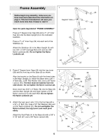
15. Feed the bolt on the end of the High Cable (73) up through the wide slot in the Top Frame (1) as shown. Wrap the High Cable around two 4Ó Pulleys (35). Attach the Pulleys inside the slot in the Top Frame with two 3/8Ó x 2 1/2Ó Bolts (54), four 3/8Ó Flat Washers (55), four 5/8Ó x 1/2Ó Pulley Bushings (42), and two 3/8Ó Nylon Jamnuts (63). See the inset drawing. Thread the bolt on the High Cable (73) two turns into the top of the Weight Tube (36). 15 42 63 1 42 35 73 73 Bolt 36 55 54 16. Locate the Low Cable (72), which is the only remaining Cable. Note that it has a large ball on one end and a small ball on the other. Route the small ball on the Low Cable (72) through the indicated slots in the Leg Lever (29) and the front leg on the Base (8). Attach a 4Ó Pulley (35) inside the slot in the front leg of the Base (8) with a 3/8Ó x 2 1/2Ó Bolt (54), two 3/8Ó Flat Washers (55), two 5/8Ó x 1/2Ó Pulley Bushings (42), and a 3/8Ó Nylon Jamnut (63). 17. Attach a 4Ó Pulley (35) inside the slot in the Leg Lever (29) with a 3/8Ó x 2 1/2Ó Bolt (54), two 3/8Ó Flat Washers (55), two 5/8Ó x 1/2Ó Pulley Bushings (42), and a 3/8Ó Nylon Jamnut (63). Attach the Spacer (94) inside the bottom of the Leg Lever (29) with a 5/16Ó x 2 1/2Ó Bolt (96), two 5/16Ó Washers (80), and a 5/16Ó Nylon Jamnut (79). Refer to the inset drawing. Press the Tab (93) onto the cage as shown. Secure the Tab to the cage with a 1/4Ó x 1Ó Bolt (98), a Fender Washer (97), and a 1/4Ó Nylon Locknut (25). Make sure that the Low Cable (72) is on top of the Spacer and the Tab. Press a 2Ó Square Inner Cap (33) into the bottom of the Leg Lever (29). 16 72 35 8 42 63 55 Slots 29 42 54 55 Large Ball 17 29 Cage 54 55 42 35 72 80 42 98 55 63 79 94 96 72 93 97 33 25 Note: It may be easier to attach the Spacer (94) 18 and the 2Ó Square Inner Cap (33) if you pivot the Leg Lever (29) to a vertical position. 18. Route the Low Cable (72) through the indicated slot in the Main Upright (3) and the Base (8). 35 62 Wrap the Low Cable (72) around a 4Ó Pulley (35) in the direction shown. Attach the Pulley inside the welded bracket on the Main Upright (3) with a 3/8Ó x 2Ó Bolt (62) and a 3/8Ó Nylon Locknut (50). 72 50 3 Slot 8 11
-
 1
1 -
2
-
3
-
4
-
5
-
 6
6 -
 7
7 -
 8
8 -
 9
9 -
 10
10 -
 11
11 -
 12
12 -
 13
13 -
 14
14 -
 15
15 -
 16
16 -
17
-
18
-
19
-
20
-
21
-
22
-
23
-
24
-
25
 |
 |
