NordicTrack Grt400 English Manual - Page 7
Attach the Chin-up Bar 13 and two Joint Plates 6
 |
View all NordicTrack Grt400 manuals
Add to My Manuals
Save this manual to your list of manuals |
Page 7 highlights
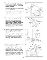
3. Attach one of the Front Uprights (7) and two Joint Plates (6) to the Left Base (3) using four M10 x 3 78mm Bolts (31) and four M10 Nylon Locknuts (29). Make sure the Front Upright is oriented so that the holes on the bottom of the Front Upright and the holes in the Joint Plates line up. If they do not line up, turn the Front Upright upside- down. Do not tighten the Nylon Locknuts yet. Make sure the Front Upright is turned so the adjustment holes are facing the Rear Upright 1 (8). Attach the other Front Upright (7, not shown) and two Joint Plates (6, not shown) to the Right Base 31 (1) in the same manner. Tap a 60mm Square Inner Cap (28) into the top of each of the Front Uprights (7). 6 4. Refer to drawing 4a. Press Square Bushings (21) into the top and bottom of one of the Weight Rests 4a (19) and one of the Weight Spotters (20) as shown. Pull out the Adjustment Knobs (22) and slide the Weight Spotter and the Weight Rest down over the 19 right Uprights (7, 8) as indicated. Refer to drawing 4b. Secure the Weight Spotter (20) and the Weight Rest (19) to the right Uprights (7, 8) by snapping each of the three Adjustment 20 Knobs (22) into one of the adjustment holes in the Uprights and turning them clockwise until tight. Assemble the other Weight Spotter (20) and Weight Rest (19) to the left Uprights (7, 8) in the same manner. Make sure both Weight Spotters and both Weight Rests are at the same height. 21 22 21 22 21 8 7 28 8 7 Adjustment Holes 29 3 6 29 4b 7 8 19 22 20 22 5. Attach the Chin-up Bar (13) and two Joint Plates (6) to the Front Uprights (7) using four M10 x 78mm 5 Bolts (31) and four M10 Nylon Locknuts (29). Do not tighten the Nylon Locknuts yet. 29 6 13 31 6 31 7 7 29 7
-
 1
1 -
 2
2 -
 3
3 -
 4
4 -
 5
5 -
 6
6 -
 7
7 -
 8
8 -
 9
9 -
 10
10 -
 11
11 -
 12
12 -
13
-
14
-
15
-
16
-
17
-
18
-
19
 |
 |
