Olympus FE 210 FE-210 Advanced Manual (English) - Page 66
Camera diagram, Camera, Appendix - battery cover diagram
 |
UPC - 050332159914
View all Olympus FE 210 manuals
Add to My Manuals
Save this manual to your list of manuals |
Page 66 highlights
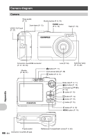
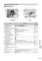
Camera diagram Camera Strap eyelet (P. 3) Shutter button (P. 8, 10) VIDEO OUT jack (P. 27) Zoom lever (P. 13) o button (P. 5, 10) Flash (P. 15) Connector cover/USB connector (P. 27, 29, 40) Monitor (P. 26, 61) Lens (P. 54) K button (P. 11) Card access lamp (P. 49) q button (P. 9, 11) Self-timer lamp (P. 15, 49) Mode dial (P. 5, 11) F/< button (P. 14) Arrow pad (ONXY) (P. 14) # button (P. 15) H button (P. 14) & button (P. 14) Y button (P. 15) S button (P. 9, 15) MENU button (P. 14) Appendix Tripod socket 66 Connector cover/DC-IN jack EN Battery/card compartment cover (P. 4, 56)
-
 1
1 -
2
-
3
-
4
-
5
-
6
-
7
-
8
-
9
-
10
-
11
-
12
-
13
-
14
-
15
-
16
-
17
-
18
-
19
-
20
-
21
-
22
-
23
-
24
-
25
-
26
-
27
-
28
-
29
-
30
-
31
-
32
-
33
-
34
-
35
-
36
-
37
-
38
-
39
-
40
-
41
-
42
-
43
-
44
-
45
-
46
-
47
-
48
-
49
-
50
-
51
-
52
-
53
-
54
-
55
-
56
-
57
-
58
-
59
-
60
-
 61
61 -
 62
62 -
 63
63 -
 64
64 -
 65
65 -
 66
66 -
 67
67 -
 68
68 -
 69
69 -
 70
70 -
 71
71 -
72
 |
 |

66
EN
Appendix
Camera diagram
Camera
Flash (P. 15)
Shutter button (P. 8, 10)
Self-timer lamp
(P. 15, 49)
Lens (P. 54)
Zoom lever (P. 13)
Mode dial (P. 5, 11)
Arrow pad (
ON
XY
)
(P. 14)
Strap eyelet
(P. 3)
Battery/card compartment cover (P. 4, 56)
Tripod socket
Connector cover/USB connector
(P. 27, 29, 40)
S
button (P. 9, 15)
Monitor
(P. 26, 61)
MENU
button (P. 14)
o
button
(P. 5, 10)
Connector cover/DC-IN jack
q
button (P. 9, 11)
K
button (P. 11)
Card access lamp (P. 49)
VIDEO OUT jack
(P. 27)
F
/
<
button (P. 14)
H
button (P. 14)
&
button (P. 14)
Y
button (P. 15)
#
button (P. 15)