Optoma EP749 User Manual
Optoma EP749 Manual
 |
View all Optoma EP749 manuals
Add to My Manuals
Save this manual to your list of manuals |
Optoma EP749 manual content summary:
- Optoma EP749 | User Manual - Page 1
lists the general notices of your Projector. FCC notice This device has been tested and found to comply with the limits for a Class B digital device pursuant to Part , which can be determined by turning the device off and on, the user is encouraged to try to correct the interference by one or more of - Optoma EP749 | User Manual - Page 2
complies with Part 15 of the FCC Rules. Operation is subject to the following two conditions: 1. this device may not cause harmful interference, and 2. this device must accept any interference received, including interference that may cause undesired operation. Notice: Canadian users This Class - Optoma EP749 | User Manual - Page 3
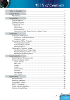
15 Adjusting Projected Image Size 15 User Controls 16 Control Panel & Remote Control 16 On-Screen Display Menus 18 How to Operate ...18 Menu Tree...19 Image-I ...20 Image-II ...22 Colour Setting ...24 Language ...26 Management ...27 Lamp Setting...30 Appendices 32 Troubleshooting 32 Replacing - Optoma EP749 | User Manual - Page 4
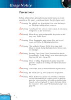
Display "Lamp Setting" menu after replacing the lamp module (refer to page 30). Warning- When switching the projector off, please ensure the projector completes its cooling cycle before disconnecting power. Warning- Turn on the projector first and then the signal sources. Warning- Do not use lens - Optoma EP749 | User Manual - Page 5
Usage Notice Do: Turn off the product before cleaning. Use a soft cloth moistened with mild detergent to clean the display housing. Disconnect the power plug from AC outlet if the product is not being used for a long period of time. Don't: Block the slots and openings on the unit - Optoma EP749 | User Manual - Page 6
DLP® projector. Outstanding features include: True XGA, 1024 x 768 addressable pixels Texas Instruments Single chip DLP® Technology NTSC/NTSC4.43/PAL/PAL-M/PAL-N/SECAM and HDTV compatible (480i/p, 576i/p, 720p, 1080i) Multi-Auto functions: Auto detection, Automatic saving of user adjustments - Optoma EP749 | User Manual - Page 7
with lens cap Power Cord 1.8m VGA Cable 1.8m Composite Video Cable 1.8m Due to the difference in applications for each country, some regions may have different accessories. Wireless Remote Controller Carry Bag 2 x AA Batteries RS232 Cable 1.8m Documents : User's Guide Quick Start - Optoma EP749 | User Manual - Page 8
Introduction Product Overview Main Unit 1 2 3 4 7 65 2 8 1 9 8 English 1. Control Panel 2. Zoom Lever 3. Power Socket 4. Focus Ring 5. Elevator Foot 6. Elevator Button 7. IR Receiver 8. Tilt Adjusting Feet 9. Connection Ports 6 - Optoma EP749 | User Manual - Page 9
Introduction Control Panel 1 2 3 4 7 5 6 7 89 10 1. Power/Standby LED 2. Temp Indicator LED 3. Lamp Indicator LED 4. Enter 5. Menu (On/Off) 6. Source Select 7. Keystone +/8. Re-Sync 9. Four Directional Select Keys 10. Power/Standby 7 English - Optoma EP749 | User Manual - Page 10
Introduction Connection Ports 81 2 345 6 7 8 9 10 1. DVI-D Input Connector (PC Digital/HDTV/HDCP Input) 2. VGA1-In SCARTConnector (PC Analog signal/SCART RGB/HD/Component Video Input) 3. Audio Input Connector 4. S-Video Input Connector 5. Composite Video Input Connector 6. Monitor - Optoma EP749 | User Manual - Page 11
Introduction Remote Control with Mouse Function and Laser Pointer 1 2 1. Freeze 2. Volume +/- 8 3 3. Power 4. Re-Sync 9 4 5. Display Mode 10 5 6. Keystone +/- 7. Four Directional Select Keys & Number But- 11 6 tons (0~3) 7 8. Laser Button 9. AV Mute 12 10. Wide Mode 11. Zoom In - Optoma EP749 | User Manual - Page 12
Installation Connecting the Projector Connect the Computer/Notebook VGA RS232 1 5 43 2 6 Audio Output (For Active Speakers) Due to the differ- 1...Power Cord ence in applications 2...RS232 Cable for each country, 3 Audio Input Cable some regions may 4 VGA to VGA Cable have different - Optoma EP749 | User Manual - Page 13
- (For Active Speakers) ence in applications for each country, some regions may DVD Player, Set-top Box, HDTV receiver have different acces- sories. 1...Power Cord 2 Composite Video Cable 3...S-Video Cable 4 SCART VGA/S-Video Adapter 5 Audio Input Cable 6 RCA Component Cable for YPbPr - Optoma EP749 | User Manual - Page 14
Text Pattern Powering On/Off the Projector Powering On the Projector 1. Remove the lens cap. 2. Ensure that the power cord and signal cable are securely connected. The Power LED will turn red. 3. Turn on the lamp by pressing "Power/Standby" button on the control panel. And the Power LED will - Optoma EP749 | User Manual - Page 15
shut itself down. When the "LAMP" indicator turns red, it indicates a problem with the lamp. Turn off the projector and disconnect the power cord from the electrical outlet, then contact your local dealer or our service center. See page 40. When the "LAMP" indicator flashes red, it indicates the - Optoma EP749 | User Manual - Page 16
The projector is equipped with elevator foot for adjusting the image height. To raise the image: 1. Press the elevator button . 2. Raise the image to the desired height angle , then release the button to lock the elevator foot into position. 3. Use screw in feet to fine-tune the display angle - Optoma EP749 | User Manual - Page 17
The projector will focus at distances from 3.9 to 39.4 feet (1.2 to 12.0 meters). Zoom Lever Focus Ring Adjusting Projection Image 40" (26.4cm) Distance 3.9' (1.2m) 9.8' (3.0m) 16.4' (5.0m) This graph is for user's reference only. 203.3"(516.3cm) 184.9"(469.6cm) 162.6" x 122" 413.0 x 309.8cm - Optoma EP749 | User Manual - Page 18
User Controls Control Panel & Remote Control There are two ways for you to control the functions: Remote Control and Control Panel. Using the Control Panel Power/Standby Source Menu Four Directional Select Keys Enter Keystone Re-Sync Refer to the "Power On/Off the Projector" section on pages 12-13 - Optoma EP749 | User Manual - Page 19
Remote Control Power Refer to the "Power On/Off the Projector" section on pages 12-13. Re-Sync Automatically synchronizes the projector to the input source. Keystone Laser Button AV Mute Volume +/Freeze Display Mode Wide Zoom In Zoom Out Four Directional Select Keys Menu Clear Enter Adjusts - Optoma EP749 | User Manual - Page 20
User Controls On Screen Display Menus The Projector has multilingual On Screen Display menus that allow you to make image adjustments and change a variety of settings. The projector will automatically detect the source. How to Operate 1. To open the OSD menu, press "Menu" on the Remote Control or - Optoma EP749 | User Manual - Page 21
Menu Tree User Controls 19 English - Optoma EP749 | User Manual - Page 22
: Memorize user's settings. Brightness Adjust the brightness of the image. Press the to darken image. Press the to lighten the image. Contrast The contrast controls the degree of difference between the lightest and darkest parts of the picture. Adjusting the contrast changes the amount of black - Optoma EP749 | User Manual - Page 23
are only supported under Video mode. Colour Temperature Adjusts the colour temperature. At higher temperature, the screen looks colder; at lower temperature, the screen looks warmer. Each display mode has its own colour temperature and can memorize user's selection. For example: Display mode PC - Optoma EP749 | User Manual - Page 24
: The input source will be scaled to fit the projection screen. 16:9 : The input source will be scaled to fit the width of the screen. LBX: This format is for non-16x9, letterbox source and for users who use external 16x9 lens to display 2.35:1 aspect ratio using full resolution. Window: When - Optoma EP749 | User Manual - Page 25
Input Signal User Controls Display area Picture area Display on Screen Ver. Shift (16:9): Image Position at window mode will also be moved accordingly. Ver. Shift (16:9) Adjust the image position up or down, when you select the aspect ratio of 16:9. Press the to move the image down. Press - Optoma EP749 | User Manual - Page 26
Red Full Range: + Red When you adjust the colour setting item, the colour temperature will be set as "User" automatically. And this set "User" is the same for all display mode. For example: Icon L M U S H Colour Temp. Low Mid User sRGB High PC Photo Movie sRGB User LMU S H LMU S H LMU S H LMU - Optoma EP749 | User Manual - Page 27
(480i/576i) Video / S-Video When we adjust color setting the current color temperature will be memorized before it auto switch to "User". Because the memorized color temperature will be a base of "User". For example: 1.) Colour temp. is Mid 2.) User creates his favorite color based on "Mid" setting - Optoma EP749 | User Manual - Page 28
User Controls Language Language Choose the multilingual OSD menu. Use the your preferred language. Press "Enter" to finalize the selection. or key to select 26 English - Optoma EP749 | User Manual - Page 29
the image upside down for ceiling-mounted projection. Rear-Ceiling When you select this function, the projector reverses and turns the image upside down. You can project from behind a translucent screen with ceiling mounted projection. Source Lock On: The projector will search specified - Optoma EP749 | User Manual - Page 30
User Controls Volume Press to decrease the volume. Press to increase the volume. Keystone (Keystone Correction) Adjusts image distortion caused by tilting projector. (±16 degrees) Digital Zoom Press the to reduce the size of an image. Press the to magnify an image on the projection screen. - Optoma EP749 | User Manual - Page 31
elapsed you will be requested to enter your password again (Use number buttons on remote. To change password, follow change password instructions above). ■ Enable: Choose "Enable" to enable security verification when turning on the projector. ■ Disable: Choose "Disable" to be able to switch on the - Optoma EP749 | User Manual - Page 32
User Controls Lamp Setting Projection Hours Displays the projection time. Lamp Hours Displays the cumulative lamp operating time. Reset Lamp Hours Resets the lamp life hour counter after replacing the lamp. Lamp Reminder Choose this function to show or to hide the warning message when the changing - Optoma EP749 | User Manual - Page 33
Appendices Sleep Timer Sets the countdown timer interval. The timer will begin, with or without a signal input. Then the projector will automatically power off then the sleep timer countdown has finished. 31 English - Optoma EP749 | User Manual - Page 34
crooked or broken. Check if the projection lamp has been securely installed. Please refer to the "Replacing the lamp" section. Make sure you have removed the lens cap and the projector is switched on. Ensure that the "AV Mute" feature is not turned on. Problem: Left of right edge of the image - Optoma EP749 | User Manual - Page 35
computer. Problem: Image has vertical flickering bar Use "Frequency" to make an adjustment. (See page 22) Check and reconfigure the display mode of your graphic card to make it compatible with the product. Problem: Image is out of focus Adjusts the Focus Ring on the projector lens. 33 English - Optoma EP749 | User Manual - Page 36
sound. If this happens, the projector will not turn on until the lamp module has been replaced. To replace the lamp, follow the procedures in the "Replacing the Lamp". (See page 36) Problem: LED lighting message Message Standby State (Input power cord) Power-LED (Green) (Red) Warming Flashing - Optoma EP749 | User Manual - Page 37
Appendices Problem: Message Reminders Fan fail: Over temperature: Power Off: Replace the lamp: 35 English - Optoma EP749 | User Manual - Page 38
or touch the lamp bulb. The bulb may shatter and cause injury if it is dropped. Lamp Replacement Procedure: 1. Switch off the power to the projector by pressing the Power/ Standby button. 2. Allow the projector to cool down for at least 30 minutes. 3. Disconnect the power cord. 4. Use a screwdriver - Optoma EP749 | User Manual - Page 39
VGA VESA VGA VESA VGA VESA VGA VESA VGA VESA VGA VESA VGA VESA SVGA VESA SVGA VESA SVGA VESA SVGA VESA SVGA VESA XGA VESA XGA VESA XGA VESA XGA * VESA SXGA * VESA SXGA * VESA SXGA * VESA SXGA * VESA SXGA * VESA SXGA+ MAC LC 13" MAC II 13" MAC 16" MAC 19" * MAC - Optoma EP749 | User Manual - Page 40
Appendices RS232 Commands RS232 Connector 3 VGA-In Connector 2 1 Pin no. 1 2 3 Name TXD RXD GND I/O (From Projector Side OUT IN __ 54321 10 9 8 7 6 15 14 13 12 11 Pin no. 1 2 3 4 5 6 7 8 9 10 11 12 13 14 15 Spec. R(RED)/Cr G(GREEN)/Y B(BLUE)/Cb NC GND GND GND GND DDC 5V HOT_DET NC DDC Date - Optoma EP749 | User Manual - Page 41
30 50.30 73.46 Warning: 1. If you buy the ceiling mount from another 50.05 manufacturer, please ensure that there is at least 10cm distance be- tween the bottom cover of the projector and the ceiling. 2. Avoid placing the projector near sources of heat such as air- Max./Min. 602.5/402 - Optoma EP749 | User Manual - Page 42
Global Offices For service or support please contact your local office. USA 715 Sycamore Drive Milpitas, CA 95035, USA www.optomausa.com Tel : 408-383-3700 Fax: 408-383-3702 Service : [email protected] Canada 120 West Beaver Creek Road Unit #9 Richmond Hill, ON L4B 1L2, Canada Tel : 905-882
-
 1
1 -
 2
2 -
 3
3 -
 4
4 -
 5
5 -
 6
6 -
 7
7 -
8
-
9
-
10
-
11
-
12
-
13
-
14
-
15
-
16
-
17
-
18
-
19
-
20
-
21
-
22
-
23
-
24
-
25
-
26
-
27
-
28
-
29
-
30
-
31
-
32
-
33
-
34
-
35
-
36
-
37
-
38
-
39
-
40
-
41
-
42
 |
 |

Regulation & safety notices
This appendix lists the general notices of your Projector.
FCC notice
This device has been tested and found to comply with the limits for a Class B digital
device pursuant to Part 15 of the FCC rules. These limits are designed to provide rea-
sonable protection against harmful interference in a residential installation. This de-
vice generates, uses, and can radiate radio frequency energy and, if not installed and
used in accordance with the instructions, may cause harmful interference to radio
communications.
However, there is no guarantee that interference will not occur in a particular instal-
lation. If this device does cause harmful interference to radio or television reception,
which can be determined by turning the device off and on, the user is encouraged to
try to correct the interference by one or more of the following measures:
• Reorient or relocate the receiving antenna.
• Increase the separation between the device and receiver.
• Connect the device into an outlet on a circuit different from that to
which the receiver is connected.
• Consult the dealer or an experienced radio/television technician for
help.
Notice: Shielded cables
All connections to other computing devices must be made using shielded cables to
maintain compliance with FCC regulations.
Caution
Changes or modifications not expressly approved by the manufacturer could void
the user’s authority, which is granted by the Federal Communications Commission,
to operate this computer.