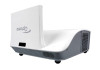
Optoma W307UST User's Manual - Page 10
Input/Output Connections, Left/Right RCA Audio Input Connector For S-Video Con
 |
View all Optoma W307UST manuals
Add to My Manuals
Save this manual to your list of manuals |
Page 10 highlights
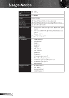
Introduction 1 2 Input/Output Connections 3 4 5 6 78 LAN 9 10 11 12 13 14 15 16 17 English 10 1. Mini USB Connector 2. HDMI Connector 3. VGA Output Connector 4. LAN Connector 5. Audio In 1 Connector (For VGA In 1 Connector) 6. S-Video Connector 7. Left/Right RCA Audio Input Connector (For S-Video Con- nector) 8. Audio Output Connector 9. 12V Trigger Relay Connector (12V, 250mA) 10. RS232 Connector 11. VGA In 1 Connector 12. VGA In 2 Connector 13. Audio In 2 Connector (For VGA In 2 Connector) 14. Composite Video Input Connector 15. Left/Right RCA Audio Input Connector (For Composite Video Input Connector) 16. 3.5mm Microphone Input Connector 17. Power Socket
-
 1
1 -
2
-
3
-
4
-
 5
5 -
 6
6 -
 7
7 -
 8
8 -
 9
9 -
 10
10 -
 11
11 -
 12
12 -
 13
13 -
 14
14 -
 15
15 -
16
-
17
-
18
-
19
-
20
-
21
-
22
-
23
-
24
-
25
-
26
-
27
-
28
-
29
-
30
-
31
-
32
-
33
-
34
-
35
-
36
-
37
-
38
-
39
-
40
-
41
-
42
-
43
-
44
-
45
-
46
-
47
-
48
-
49
-
50
-
51
-
52
-
53
-
54
-
55
-
56
-
57
-
58
-
59
-
60
-
61
 |
 |

10
English
Introduction
Input/Output Connections
Mini USB Connector
1.
HDMI Connector
2.
VGA Output Connector
3.
LAN Connector
4.
Audio In 1 Connector (For VGA In 1 Connector)
5.
S-Video Connector
6.
Left/Right RCA Audio Input Connector (For S-Video Con
-
7.
nector)
Audio Output Connector
8.
12V Trigger Relay Connector (12V, 250mA)
9.
RS232 Connector
10.
VGA In 1 Connector
11.
VGA In 2 Connector
12.
Audio In 2 Connector (For VGA In 2 Connector)
13.
Composite Video Input Connector
14.
Left/Right RCA Audio Input Connector (For Composite
15.
Video Input Connector)
3.5mm Microphone Input Connector
16.
Power Socket
17.
LAN
3
2
1
5
6
8
9
10
7
11
12
13
14
15
16
17
4