Panasonic BL-C210A Installation Guide - Page 1
Panasonic BL-C210A Manual
 |
View all Panasonic BL-C210A manuals
Add to My Manuals
Save this manual to your list of manuals |
Page 1 highlights
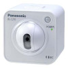
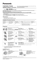
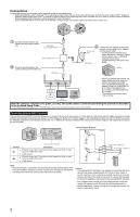
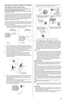
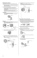
Installation Guide Network Camera Indoor Use Only Please read this document before using the product, and save this document for future reference. Panasonic Network Camera Website: http://panasonic.net/pcc/ipcam/ BL-C210 Model No. (Wired Type) Model number suffixes ("A", "CE", and "E") are omitted from the following model numbers shown in this document, unless necessary. BL-C210A, BL-C210CE, BL-C210E Please read the included Important Information before proceeding. Complete Operating Instructions and all other documentation can be found on the included CD-ROM. • This document (Installation Guide) explains how to physically connect the camera to the power supply and network, as well how to mount or place the camera for regular use. • The Setup Guide describes how to set up the camera so that it can be accessed using a PC. • Refer to the Operating Instructions on the CD-ROM for details regarding the camera's features. • Refer to the Troubleshooting Guide on the CD-ROM if you have any problems configuring or using the camera. Abbreviations • UPnP is the abbreviation for "Universal Plug and Play". • The Network Camera is referred to as "the camera" in this document. • The Setup CD-ROM is referred to as "the CD-ROM" in this document. Installation Procedure Overview The following is an overview of the steps required to install and setup the camera. All steps are explained in this document unless otherwise noted. Preparation Confirm that you have all the items required for installation. Camera Diagram Make sure you know the names of the camera's physical features. Connections Connecting the camera to your network and to the power outlet. Setup • Refer to the included Setup Guide for information on configuring the camera to be accessed from a PC. • BL-C210A only: Refer to the included Setup Guide for VIERA Connection for information on registering the camera to a Panasonic VIERA TV. Mounting Mounting or placing the camera. Preparation 1. Confirm the following items are included in the camera's packaging. BL-C210A BL-C210CE BL-C210E Main Unit (1 pc.) The appearance of your camera depends on which model you have purchased. AC Adaptor (1 pc.) Order No. PQLV206Y Cord Length: About 3 m (9 feet 10 inches) BL-C210A Order No. PQLV206CEY Cord Length: About 3 m (9 feet 10 inches) BL-C210CE Screw A (3 pcs.) Order No. XTB4+20AFJ Used when securing the safety wire to the wall. Screw B (1 pc.) Order No. XTB26+10GFJ Used for securing the safety wire to the camera. Screw C (2 pcs.) Order No. PQHE5004X Used for wall mounting the camera. Washer S (2 pcs.) Order No. XWG35FJ Used when mounting the camera to the wall. Washer M (1 pc.) Order No. XWG26D12VW Used when securing the safety wire to the camera. Washer L (1 pc.) Order No. XWG4F16VW Used when securing the safety wire to the wall. Order No. PQLV206EY Cord Length: About 3 m (9 feet 10 inches) BL-C210E Power Transfer Unit (1 pc.) Order No. PNWEC210A BL-C210A Order No. PNWP3C160A BL-C210CE, BL-C210E Used to power the camera. Safety Wire (1 pc.) Order No. PQME10080Z Used to secure the camera when wall mounting it. Important Information (1 pc.) Installation Guide (this document) (1 pc.) Setup Guide (1 pc.) Setup Guide (for VIERA Connection) (1pc.) [BL-C210A Only] Setup CD-ROM (1 pc.) Order No. PNQC1016R Contains the Setup Program needed to configure the camera, as well as the camera's documentation.* *See the included Important Information for a description of each document. 2. You will need the following additional items to install and configure the camera. - a PC (see the system requirements in the Important Information document) - 2 LAN cables (CAT-5 straight cable) - a router Camera Diagrams Front View Rear View A PRIVACY button*1 A B Built-in sensor (pyroelectric infrared sensor) C Speaker (for built-in alarm) B D POWER indicator*2 C E AV LINK indicator*3 F Microphone H G D G Lens cover H Lens FE I J K L M ON *1 See "PRIVACY Button" on page 3 for information about the PRIVACY button. *2 See 1.1 Understanding the Camera Indicators in the Troubleshooting Guide on the CD-ROM for indicator meaning. *3 BL-C210A only I Wall mounting holes J Tripod mounting hole K Serial number and MAC address label L DATA/POWER IN M External INPUT interface N FACTORY DEFAULT RESET button P O Safety wire hole P Cable cover © Panasonic System Networks Co., Ltd. 2009 PNQX1993YB KK0809CQ4119
-
 1
1 -
 2
2 -
 3
3 -
 4
4
 |
 |
