Panasonic BL-C210A Installation Guide - Page 4
Mounting the Camera
 |
View all Panasonic BL-C210A manuals
Add to My Manuals
Save this manual to your list of manuals |
Page 4 highlights
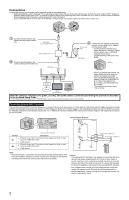
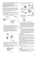
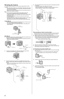
Mounting the Camera • The camera illustrations in this document depict the BL-C210A. Caution • Do not drive the screws into a soft material. Drive the screws into a secure area of the wall, such as a wall stud, otherwise the camera may fall and be damaged. • Make sure you attach the safety wire when mounting the camera, to prevent the camera from falling. Note • Use screws that are appropriate for the material of the wall. • The included screws are for use with wooden walls only. • The pull-out strength of the installation area must be at least 294 N (30 kgf) per screw. • The camera is intended for indoor use only and should not be mounted outdoors. • To ensure that camera images are displayed properly, do not mount the camera on an incline. Mount the camera so that it is perpendicular to the floor. Do not mount the camera upside down. Tripod Mount • Do not use a tripod screw with a thread of 6 mm (1/4 inch) or more. This may damage the tripod mounting hole. • The camera cannot be mounted depending on the shape of the camera platform. Tripod mounting hole 4. Secure the safety wire to the wall using screw A (included) and washer L (included). • Leave some slack in the safety wire, as shown. • Attach the safety wire in a position so that if the camera were to become detached, it would not fall on nearby people. Screw A Washer L At least 25 mm (1 inch) Safety wire 4 mm (3/16 inch) Tripod (customer-provided) Wall Mount 1. Remove the cable cover, secure the safety wire to the camera using screw B (included) and washer M (included). • Make sure you attach the safety wire when mounting the camera, to prevent the camera from falling. When mounting on a mortar or concrete surface • Prepare anchors for a 4 mm (3/16 inch) diameter screw for the safety wire, and 3.5 mm (1/8 inch) diameter screws for the wall mounting. 1. Mark the points where you are going to make holes. 2. Make holes with an electric drill. Insert anchors (customer-provided) into the holes and use a hammer to make them flush with the wall. • Mortar walls break easily when drilling. Be careful of pieces of mortar which may become loose and fall. Drill for concrete (in case of tile, use a drill for tile) Cable cover Safety wire Washer M Screw B 2. Connect a LAN cable to the camera and attach the cable cover. • Insert the LAN cable until it clicks into to place. 3. Mount the camera by following the instructions on this page. 4. Mark the point where you are going to make a hole for the safety wire, follow step 2 and secure the safety wire. Connecting to the power transfer unit 1. Connect a LAN cable to the power transfer unit and to the switching hub, router, etc. • The power transfer unit can be fixed in place with 2 pieces from screw A (included) (4 mm x 20 mm [3/16 inch x 13/16 inch]). 3. Mount the camera on the screws by inserting the screws into the camera's wall mounting holes, then sliding the camera down until it is secure. • Leave 2 mm (1/16 inch) of space between the screw heads and the washers, as shown below. Screw C Washer S 29 mm (1 1/8 inches) At least 25 mm (1 inch) LAN Cable 2. Connect a LAN cable from the camera to the power transfer unit. 3. Connect the AC adaptor to the power transfer unit and plug the other end into the power outlet. • The camera will activate. To the power outlet 9 mm (3/8 inch) 3.5 mm (1/8 inch) 2 mm (1/16 inch) Hook for AC adaptor To router 4
-
 1
1 -
 2
2 -
 3
3 -
 4
4
 |
 |
