Panasonic CF-73SCUTSBM Service Manual
Panasonic CF-73SCUTSBM - Toughbook 73 - Pentium M 1.86 GHz Manual
 |
UPC - 092281843346
View all Panasonic CF-73SCUTSBM manuals
Add to My Manuals
Save this manual to your list of manuals |
Panasonic CF-73SCUTSBM manual content summary:
- Panasonic CF-73SCUTSBM | Service Manual - Page 1
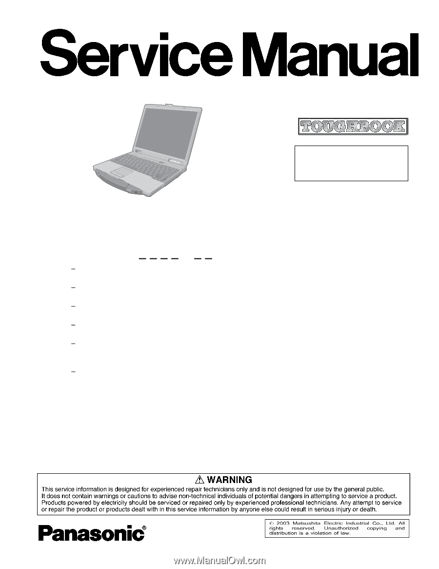
ORDER NO. CPD0304020C1 Notebook Computer CF-73 This is the Service Manual for the following areas. M ...for U.S.A. and Canada Model Number Reference The following models are numbered in accordance with the types of CPU, LCD and HDD etc. featured by product. Model No. CF-731 2 3 4 X 5 6 1: CPU type - Panasonic CF-73SCUTSBM | Service Manual - Page 2
2-1 - Panasonic CF-73SCUTSBM | Service Manual - Page 3
enclosing cover. It should never be used as a stand alone drive. Danger: The serviceman should not remove the cover of drive unit and should not service because the drive unit is a nonserviceable part. Please check DANGER label on PD-drive unit. • Unplug the AC power cord to the equipment before - Panasonic CF-73SCUTSBM | Service Manual - Page 4
2-3 - Panasonic CF-73SCUTSBM | Service Manual - Page 5
2-4 - Panasonic CF-73SCUTSBM | Service Manual - Page 6
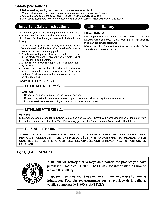
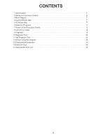
CONTENTS 1 Specifications 4 2 Names and Functions of Parts 6 3 Block Diagram 8 4 System Memory Map 9 5 I/O Adress Map 10 6 Diagnosis Procedure 11 7 Power-On Self Test (Boot Check 12 8 List of Error Codes 13 9 Diagnosis 15 10 Diagnostic Test 22 11 Self Diagnosis Test 23 12 Wiring - Panasonic CF-73SCUTSBM | Service Manual - Page 7
1 Specfication 4 - Panasonic CF-73SCUTSBM | Service Manual - Page 8
- Panasonic CF-73SCUTSBM | Service Manual - Page 9
2 Names and Functions of Parts Wireless LAN Antenna LCD Power Switch Before using the computer for the first time, carefully read the [LIMITED USE LICENSE AGREEMENT]. If you agree to the conditions, remove the seal. PC Card Slots USB Ports Function Keys For information on the key combinations - Panasonic CF-73SCUTSBM | Service Manual - Page 10
Modem I/O Box Connector For connecting printer, external mouse, keyboard, etc., through the I/O box (optional). Ventilation Hole This hole allows heat to exit. CAUTION Do not block or place the computer in a location that may prevent proper ventilation. LAN MP Release Button Headphone Jack Use this - Panasonic CF-73SCUTSBM | Service Manual - Page 11
3 Block Diagram System Confugration Diagram 8 - Panasonic CF-73SCUTSBM | Service Manual - Page 12
4 9 - Panasonic CF-73SCUTSBM | Service Manual - Page 13
5 I/O Address Map 0x0000-0x0CF7 0x0000-0x0CF7 0x0D00-0xFFFF 0x3000-0x3FFF 0x3000-0x3FFF 0x03B0-0x03BB 0x03B0-0x03BB 0x03C0-0x03DF 0x03C0-0x03DF 0x1820-0x183F 0x1800-0x181F 0x1840-0x185F 0xFD00-0xFDFF 0xFC00-0xFCFF 0xDFF0-0xDFFF 0xFA00-0xFAFF 0xF900-0xF9FF 0x4000-0x40FF 0x0A79-0x0A79 0x0279-0x0279 - Panasonic CF-73SCUTSBM | Service Manual - Page 14
6 11 - Panasonic CF-73SCUTSBM | Service Manual - Page 15
controller error RAM error RAM error RAM error BIOS ROM error Occurrence of unexpected offering (Note) A beep sound is also issued in case of other I/O trouble. 12 - Panasonic CF-73SCUTSBM | Service Manual - Page 16
Following the list are explanations of the messages and remedies for reported problems. If your system displays one of except the messages marked below with an asterisk (*), write down the message and contact Panasonic Technical Support. If your system fails after you make changes in the Setup menus - Panasonic CF-73SCUTSBM | Service Manual - Page 17
System cache error - Cache disabled Contact Panasonic Technical Support. 02F0: CPU ID: CPU socket of the failure in System, Extended or Shadow memory. Invalid System Configuration Data Problem with NVRAM (CMOS) data. I/O device IRQ conflict I/O device IRQ conflict on the screen. 14 Troubleshooting - Panasonic CF-73SCUTSBM | Service Manual - Page 18
the unit. (When using AC) No power is sent to the unit. (When using the Battery Pack) 2 Power cuts off during operation. Troubleshooting Source of No. procedures Result problem 1-1 Is 15V applied to pins 1-3 of Q710? (Whichever one)? YES Go to No.1-3 NO Go to No.1-2 1-2 Is 15V applied to - Panasonic CF-73SCUTSBM | Service Manual - Page 19
Clock is not updating 14 Memory size/data error 15 PCI failure Troubleshooting No. procedures 4-1 Check software setting. Replace the Speakers. 4-2 Does operation return to normal? 4-3 Replace the Main PCB. Source of Result problem YES Software setting NO Go to No.4-2 YES Speakers NO Go - Panasonic CF-73SCUTSBM | Service Manual - Page 20
screen does not display properly. Display quality poor. (Fuzzy or slanted, etc.) 4 Backlight does not turn on. Troubleshooting Source of No. procedures Result problem 1-1 Does the LCD display properly after brightness level YES Brightness adjustment is adjusted? NO Go to No.1-2 Replace - Panasonic CF-73SCUTSBM | Service Manual - Page 21
to testing. No. Symptom 1 Key top cannot be pressed. Key top does not spring back after pressing. Troubleshooting No. procedures 1-1 Keyboard is broken. Result Source of problem Component Keyboard 2 None of the keys function. Replace the keyboard and Certain keys do not 2-1 see if - Panasonic CF-73SCUTSBM | Service Manual - Page 22
light. 6 Abnormal sound. 7 Hard disk failure Troubleshooting Source of No. procedures Result problem 1-1 Has the HDD been partitioned? YES Go NO HDD cable 6-1 Replace the HDD. 7-1 Does executing FDISK correct the problem? Replace the HDD. 7-2 Does operation return to normal? YES NO HDD - Panasonic CF-73SCUTSBM | Service Manual - Page 23
communicate with another computer when connected directly. 3 Unit will not communicate with modem. 4 Diagnostic Test reports problem in serial port. Troubleshooting Source of No. procedures Result problem 1-1 Is the COM port properly set? YES Go to No.1-2 NO Improper setting Is the same - Panasonic CF-73SCUTSBM | Service Manual - Page 24
to testing. No. Symptom 1 Access lamp does not light. 2 Cannot read from CD-ROM. 3 Tray does not open. 4 Abnormal sound. Troubleshooting Source of No. procedures Result problem Replace the CD-ROM drive. YES CD-ROM drive 1-1 Does operation return to normal? NO Go to No.1-2 Replace the - Panasonic CF-73SCUTSBM | Service Manual - Page 25
1 pc. 10.2. Preparation (1) Connect the computer to the IO BOX (CF-VEBU03). (2) Connect the AC Adapter and External Equipments. (3) The System Setup 4) with 4.7KW each. CAUTION The plug described above must be used for servicing purpose only. Do not use it for other than the above purpose and ensure - Panasonic CF-73SCUTSBM | Service Manual - Page 26
the Automatic test and Peripheraltest. Starting up the setup utility Turn on the power. When "Panasonic Press F2 to enter setup" appears on the screen, press F2. Press " " to Selection test only when necessary. Problems in the unit are located and divided according to error messages that occur during - Panasonic CF-73SCUTSBM | Service Manual - Page 27
the main DMA REGISTER TEST 9 board, etc.) DMAC TRANSFER TEST 10 PIC HALT INSTRUCTION TEST 11 PIC REGISTER TEST 12 RTC CMOS RAM TEST 13 RTC TEST 14 PIT DAM register test DAM transfer test Interrupt controller halt instruction test Interrupt controller register test Real time clock CMOS - Panasonic CF-73SCUTSBM | Service Manual - Page 28
. The test is stopped when an error occurs and the error message is displayed. For explanations of error messages, see Error Messages and Problem Categories (section 4.5). Quitting the test At the screen shown below, simultaneously press the ALT and X keys. 11.3. Peripheral Test Input screen Test - Panasonic CF-73SCUTSBM | Service Manual - Page 29
the parallel port test should you change the setup contents to those shown below. [Changing the setup utility] Turn on the power. When "Panasonic", "Press F2 to enter setup" appears on the screen, press F2. Press " " to select Advanced. Press " " to choose Mode. Press Enter, choose Bidirectional - Panasonic CF-73SCUTSBM | Service Manual - Page 30
test condition settings for to be changed, press "A" for Additional custom test items. and "R" for Erase. Example: All initial VAlues are "0" so set CF-73. TEST1. tests other than the necessary ones to "1". Press "C" twice to return the menu screen. To save the selected list, press "ALT - Panasonic CF-73SCUTSBM | Service Manual - Page 31
11.5. Error Messages and Troubleshooting The table below explains the parts that may TEST 6 (Control ICs on the DMA REGISTER TEST 7 main board, etc.) DMAC Transfer TEST 8 PIC HALT INSTRUCTION TEST 9 PIC REGISTER TEST 10 RTC CMOS RAM TEST 11 12 SPEAKER TEST 13 PIT CH0 TEST 14 PIT CH1 - Panasonic CF-73SCUTSBM | Service Manual - Page 32
12. Wiring Connection Diagram CN 1002 MIC JK 1000 HEADPHONE JK 1001 DC-IN JK 1002 CN 1001 CN 1006 SW 1001 REAR PCB LED PCB CN 1300 SW 1000 CN CN 1003 1005 CN 1000 INVERTER CN 1601 L C1N600 17C00N R CN 1701 SPEAKER PCB SPEAKER SPEAKER BATTERY PACK I/O CN 3001 I/O PCB CN 3000 FAN - Panasonic CF-73SCUTSBM | Service Manual - Page 33
13. Disassembly/Reassembly Note: Power off the computer. Do not shut down to the Suspend or hibernation mode. Do not add peripherals while the computer is in the Suspend or hibernation mode; abnormal operation may result. 13.1 Removing the Battery Pack. Latch 1 13.3 Removing the HDD Unit and the - Panasonic CF-73SCUTSBM | Service Manual - Page 34
13.5 Removing the Center Cover. Center Cover LED-PCB 1. Remove the screw . Screw : DFHE5025YA 2. Disconnect the connector (CN1300), and remove the LED-PCB. 13.7 Removing the LCD Unit. Hooks 1. Release the three Hooks. Center Cover LCD Unit Hooks CN1001 CN1006 CN801 LCD Unit 2. Open and - Panasonic CF-73SCUTSBM | Service Manual - Page 35
13.9 Removing the Bottom Cabinet. Plate 1 Top Cabinet Plate 2 13.10 Removing the MAIN-PCB and the VGA-PCB. MAIN-PCB Lithium Battery MODEM CN12 CN7 VGA-PCB CN6 PC Card Ejector 1. Remove the screw and the screw , and then - Panasonic CF-73SCUTSBM | Service Manual - Page 36
13.11 Removing the REAR-PCB, the I/O-PCB, the Fan, the LAN Cable and the MODEM Cable. LAN Cable CN1005 REAR-PCB Fan MODEM RHE ASSY 13.12 Removing the LCD Front Cabinet. LCD Front Cabinet LCD Rubbers I/O Cover Top Cabinet I/O PCB MODEM Cable - Panasonic CF-73SCUTSBM | Service Manual - Page 37
13.13 Removing the LCD, the Inverter, the Speaker, the SPEAKER-PCB and the WLAN-PCB. LCD Inverter Inverter Case Hinge L W-LAN-PCB L W-LAN-PCB R Speakers CN1601 SPEAKER-PCB L LCD Rear Cabinet SPEAKER-PCB R CN1701 Hinge R LCD Backlight 1. Remove the LCD and the - Panasonic CF-73SCUTSBM | Service Manual - Page 38
H K110 35 K81 K81 K80 E28 Screw tightening torque B 0.2 ± 0.02 N · m (2.0 ± 0.2 kgf · cm) E 0.17 ± 0.02 N · m (1.7 ± 0.2 kgf · cm) C 0.1 ± 0.01 N · m (1.0 ± 0.1 kgf · cm) H 1.2 ± 0.1 N · m (12.0 ± 1.0 kgf · cm) D 0.4 ± 0.02 N · m (4.0 ± 0.2 kgf · cm) CF-73E3KVXDM - Panasonic CF-73SCUTSBM | Service Manual - Page 39
) G 0.1 ± 0.02 N · m (1.0 ± 0.2 kgf · cm) K21 K84 K76 K75 36 B K104 B K104 A2 E29 K21 F K103 B K101 A K21 B K101 K21 K19 K2 K28-1 B K28-2 B K104 F K103 K204 CF-73E3KVXDM - Panasonic CF-73SCUTSBM | Service Manual - Page 40
B K115 K59 B K45-9 E33 B K104 E33-1 E19 E23 K58 B K115 K60 K63 K61 K41 K99 E20 K98 Screw tightening torque B 0.2 ± 0.02 N · m (2.0 ± 0.2 kgf · cm) F 0.8 ± 0.1 N · m (8.0 ± 1.0 kgf · cm) CF-73E3KVXDM - Panasonic CF-73SCUTSBM | Service Manual - Page 41
important for safety. When replacing any of these components, use only manufacturer's specified parts. CF-73E3KVXxM REF. NO and AREA Main Block Unit E 1 E 2 E 3 E R CABLE, W-LAN R AC ADAPTER BATTERY PACK AC CABLE CABLE, MODEM MANUAL CARD, WARRANTY (M2) PROTECT SHEET CUSHION, T CUSHION, B CASE, - Panasonic CF-73SCUTSBM | Service Manual - Page 42
, REA I/O 1 K 21 DFHG371ZA-0 LEG RUBBER 5 K 22 DFHG6034ZA GUIDE, MP 1 K 24 DFHE0218ZA GASKET 1 K 25 DFHE0513ZA SHEET, EMI K 45-5 DFKE0706ZA-0 COVER, LCD W LAN 1 K 45-6 DFGB0106ZA-0 LABEL, PANASONIC 1 K 45-7 DFGX0396ZA-0 DUMMY, ANTENNA COVER 1 K 45-8 DFBS0065ZA-0 LCD - Panasonic CF-73SCUTSBM | Service Manual - Page 43
SHEET, MP CAB 1 1 K 90 DFHR3532ZA SHEET, MP CAB 2 1 K 91 DFHR6070ZA COVER, WATER PROOF 1 K 92 DFHR8449ZB CUSHION, DRIVE SUPPORT 1 K 93 DFHR8455ZA SHEET, WATER PROOF 1 K 94 DFHR8456ZA SPACER, TOP 1 K 96 DFHR8458ZB DAMPER, MINI PCI 2 K 98 DFHE0277ZA GASKET, CONFIG - Panasonic CF-73SCUTSBM | Service Manual - Page 44
Note: Important Safety Notice Components identified by mark have special characteristics important for safety. When replacing any of these components use only manufacturer's specified parts. CF-73E3KVXxM REF. NO and AREA Main PCB C1 3 C4 5 7 8 9 11 12 13 15 16 17 19 20 21 24 25 26 29 30 31 33 - Panasonic CF-73SCUTSBM | Service Manual - Page 45
C121 125 130 134 195 196 198 DCUM1A1051BD CAPACITOR, 10V, 1µF 10 201 277 504 C172 173 F1G1H6R0A452 CAPACITOR, 50V, 6pF 2 C188 F1G1H7R0A452 CAPACITOR, 50V, 7pF 1 C189 F1G1H5R00004 CAPACITOR, 50V, 5pF 1 C199 407 F1G1C473A004 CAPACITOR, 16V, 0.047µF 2 C228 547 ECJ3YB1E106M - Panasonic CF-73SCUTSBM | Service Manual - Page 46
C797 F1G1E103A062 CAPACITOR, 25V, 0.01µF 1 CA1 2 EZASCE101M CAPACITOR ARRAY 2 CN2 K1MMZZB00002 CONNECTOR, MINI PCI 1 CN3 DFJP201ZA002 CONNECTOR 1 CN4 K1KBZZA00030 CONNECTOR, STACK 1 CN5 K1FB315B0008 CONNECTOR, VGA 1 CN6 K1NAF0D00002 CONNECTOR, CARD BUS 1 CN7 K1KA08B00137 - Panasonic CF-73SCUTSBM | Service Manual - Page 47
IC, VOLTAGE DETECTOR 3 IC600 C0DBAFH00019 IC, DC/DC CONTROLLER 1 IC601 C0DBALH00001 IC, DC/DC CONVERTER 1 IC602 614 C0DBZZZ00057 IC, DRIVER 2 IC605 616 C0DBAHH00009 IC, DC/DC CONVERTER 2 IC606 C0DBAFH00011 IC, DC/DC CONTROLLER 1 IC608 DA7W02UT12L0 IC, CMOS 1 IC609 - Panasonic CF-73SCUTSBM | Service Manual - Page 48
Q601 UNR9113J0L TRANSISTOR 1 Q603 607 618 619 693 694 B1DBGD000002 TRANSISTOR 6 Q604 605 608 609 B1DFGC000001 TRANSISTOR 4 Q612 613 DAFDS6912A TRANSISTOR 2 Q617 DAFDN359AN TRANSISTOR 1 Q622 623 628 630 DAFDS6912A TRANSISTOR 4 Q625 626 B1GKCFJN0004 TRANSISTOR 2 Q627 629 - Panasonic CF-73SCUTSBM | Service Manual - Page 49
R48 49 50 51 52 53 54 55 56 57 ERJ2GEJ100X RESISTER, 1/16W, 10ȍ 13 58 562 563 R59 ERJ2RKF1200X RESISTER, 1/16W, 120ȍ 1 R60 ERJ2RKF1200X RESISTER, 1/16W, 120ȍ 1 R61 DBT10KC1513P THERMISTOR 1 R62 67 106 107 118 126 154 ERJ2GEJ103X RESISTER, 1/16W, 10Kȍ 24 155 165 167 168 200 227 - Panasonic CF-73SCUTSBM | Service Manual - Page 50
R523 526 ERJ2RHD333X RESISTER, 1/16W, 33Kȍ 2 R535 RL1220SR47F RESISTER, 1/8W, 0.47ȍ 1 R536 ERJ2GEJ562X RESISTER, 1/16W, 5.6Kȍ 1 R544 ERJ3GEYJ562V RESISTER, 1/16W, 5.6Kȍ 1 R546 553 D0HA103ZA001 RESISTER, 1/16W, 10Kȍ 2 R556 558 D1BDR0470002 RESISTER, 1/8W, 0.047ȍ 2 R557 583 - Panasonic CF-73SCUTSBM | Service Manual - Page 51
R778 ERJ2RKF1503X RESISTER, 1/16W, 150Kȍ 1 R783 ERJ2GE0R00X RESISTER, 1/16W, 0ȍ 1 R784 786 ERJ2GEJ101X RESISTER, 1/16W, 100ȍ 2 R787 788 ERJ2GEJ105X RESISTER, 1/16W, 1Mȍ 2 R789 D0HA104ZA001 RESISTER, 1/16W, 100Kȍ 1 R790 D0HB154ZA002 RESISTER, 1/16W, 150Kȍ 1 R791 D0HB154ZA002 - Panasonic CF-73SCUTSBM | Service Manual - Page 52
D800 B0JCCE000002 DIODE 1 D801 EC10QS04TL DIODE 1 D802 MAZ80620ML DIODE 1 F800 K5H2021A0003 FUSE, 63V, 2A 1 IC800 C1DB00000907 IC, VGA CONTROLLER 1 IC801 C0JBZZ000297 IC, CLOCK GENERATOR 1 IC804 DA7S14UT85L0 IC, INVERTER 1 IC805 C0DBAFH00011 IC, DC/DC CONTROLLER 1 - Panasonic CF-73SCUTSBM | Service Manual - Page 53
C1064 F1H1H222A748 CAPACITOR, 50V, 2200pF 1 C1068 F1H1H221A748 CAPACITOR, 50V, 220pF 1 C1072 1074 1075 F1L1E106A017 CAPACITOR, 25V, 10µF 3 C1079 1080 1081 F1H1H104A731 CAPACITOR, 50V, 0.1µF 3 C1082 F1H1H104A731 CAPACITOR, 50V, 0.1µF 1 C1086 1087 F4Z1A107A002 CAPACITOR, 10V, 100 - Panasonic CF-73SCUTSBM | Service Manual - Page 54
R1017 1032 1057 ERJ3GEYJ473V RESISTOR, 1/16W, 47Kȍ 3 R1027 1028 1054 1091 1093 ERJ3GEYJ223V RESISTOR, 1/16W, 22Kȍ 5 R1029 1060 1069 ERJ3GEYJ472V RESISTOR, 1/16W, 4.7Kȍ 3 R1045 1100 1101 ERJ3GEYJ102V RESISTOR, 1/16W, 1Kȍ 3 R1046 ERJ3GEYJ104V RESISTOR, 1/16W, 100Kȍ 1 R1047 1055 - Panasonic CF-73SCUTSBM | Service Manual - Page 55
CN1701 DFJP201ZA002 CONNECTOR 1 IC1700 C0ABZA000039 IC, POWER AMP 1 R1700 ERJ3GEYJ100V RESISTOR, 1/16W, 10ȍ 1 R1701 1702 ERJ1TYJ5R6U RESISTOR, 1W, 5.6ȍ 2 I/O PCB C3000 F1J0J106A013 CAPACITOR, 6.3V, 10µF 1 CA3000 3001 3002 3003 3004 EZASCE181M CAPACITOR ARRAY 6 3005 CA3006 - Panasonic CF-73SCUTSBM | Service Manual - Page 56
CF-73E3 Printed Circuit Board Main PCB 1 2 3 4 5 6 7 8 9 10 11 A B C D E F G H I J - Panasonic CF-73SCUTSBM | Service Manual - Page 57
Main PCB 1 2 3 4 5 6 7 8 9 10 11 A B C D E F G H I J - Panasonic CF-73SCUTSBM | Service Manual - Page 58
1 2 VGA PCB 3 4 5 6 7 8 9 10 11 VGA PCB A B C D E F G H I J - Panasonic CF-73SCUTSBM | Service Manual - Page 59
1 Rear PCB 2 3 4 5 6 7 8 Rear PCB 9 10 11 A B C D E F G H I J - Panasonic CF-73SCUTSBM | Service Manual - Page 60
1 2 Speaker PCB R 3 4 Speaker PCB L 5 6 7 8 LED PCB 9 LED PCB 10 11 A B C Front PCB I/O PCB Front PCB I/O PCB D E F G H I J - Panasonic CF-73SCUTSBM | Service Manual - Page 61
CF-73E3 Schematic Diagram Main 1 CPU (1/2) VC18 003:F6 GTLD3_HD#[48-63] Banias 1.4G IC1 003:I1 VCPUCORE GTLD3_HD#[63] AF26 D#[63] A#[3] P4 GTLA0_HA#[3] Banias 1.4G - Panasonic CF-73SCUTSBM | Service Manual - Page 62
Main 2 CPU (2/2) 1 VCCP R281 PROCHOT# 002:B2 56 VCTREF Banias 1.4G IC1 002:E8 THERMDA B18 THERMDA GND AC10 002:E9 THERMDC A18 THERMDC GND AC8 2 010:D4 002:B1 CPU_THERMTRIP# PROCHOT# C17 THERMTRIP# B17 PROCHOT# GND AC5 GND AC2 GND AB26 003:I7;010:D4 003:I7 030:F4 CPU_DPSLP# - Panasonic CF-73SCUTSBM | Service Manual - Page 63
Main 3 MCH-M (1/2) System Memory Interface 1 2 ;007:F3;008:G1,005:A3;007:E8;008:G1,005:A3;007:B8;008:G1 SD_MA[0-12] 855PM SD_MA[0] E12 SMA0 SD_MA[1] F17 SMA1 SD_MA[2] E16 SMA2 SD_MA[3] G17 SMA3 SD_MA[4] G18 SMA4 SD_MA[5] E18 SMA5 SD_MA[6] F19 SMA6 SD_MA[7] G20 SMA7 SD_MA[8] G19 SMA8 SD_MA[9] - Panasonic CF-73SCUTSBM | Service Manual - Page 64
Main 4 MCH-M (2/2) 855PM IC2 E29 VSS VSS N15 1 7,012:F7,012:H7,012:F7,012:H7,012:F7,012:H7,012:F7,012:H7 G_AD[0-31] 855PM IC2 VC15MCH 855PM IC2 VCCP J29 VSS N29 VSS U29 VSS VSS P16 VSS R15 VSS T16 G_AD[31] AD24 G_AD31 R22 VCC1_5 VCCP AB8 AA29 VSS VSS U15 AGP Interface Hub - Panasonic CF-73SCUTSBM | Service Manual - Page 65
Main 5 Memory Resisters 1 003:D1 SD_DQ[0-63] SD_RDQ[0-63] 006:A1;007:B1;008:A1 DIMM Rt Rs DQ,DQS MCHR RDIMM Odem Rt MA,BA,WE#,RAS#,CAS# SD_DQ[0] RA8 8 9 SD_RDQ[0] SD_DQ[1] 7 10 SD_RDQ[1] Rs SD_DQ[2] 6 11 SD_RDQ[2] 2 SD_DQ[3] 5 12 SD_RDQ[3] SD_DQ[4] 4 13 - Panasonic CF-73SCUTSBM | Service Manual - Page 66
Main 6 Memory SD_RDQ[0-63] 05:D4,005:D4,005:D4,005:D4,005:D4,005:D4,005:D5,005:D5 SD_RA[0-12] 1 05:D5;006:B7;006:C1;006:C7;006:E1;006:E7;006:G1;006:G7 05:D5;006:B7;006:C1;006:C7;006:E1;006:E7;006:G1;006:G7 SD_RBA0 SD_RBA1 SD_RA[11] SD_RA[10] SD_RA[9] SD_RA[8] SD_RA[7] 2 SD_RA[6] SD_RA - Panasonic CF-73SCUTSBM | Service Manual - Page 67
Main 7 SO-DIMM 1 005:H1;006:A1;008:A1 SD_RDQ[0-63] 200 SO-DIMM 200 SO-DIMM VB25 MEMREF MEMREF VB25 VB25 CN2 CN2 VB25 2 C138 1 VREF VREF 2 0.1u 003:A1;005:A3;008:G1 SD_MA[9] 101 A9 A8 102 SD_MA[8] 003:A1;005:A3;008:G1 SD_RDQ[0] 0.1u 3 VSS 5 DQ0 VSS 4 C139 DQ4 6 SD_RDQ[4] - Panasonic CF-73SCUTSBM | Service Manual - Page 68
Main 8 Memory Terminator A1;005:A3;007:I3,003:A1;005:A3;007:F3,003:A1;005:A3;007:I3,003:A1;005:A3;007:F3,003:A1;005:A3;007:I2,003:A1;005:A3;007:F2,003:A1;005:A3;007:I2,003:A1;005:A3;007:F2,003:A1;005:A3;007:I2,003:A1;005:A3;007:F2,003:A1;005:A3;007:F3,003:A1;005:A3;007:E8,003:A1;005:A3;007:B8 1 - Panasonic CF-73SCUTSBM | Service Manual - Page 69
Main 9 CK-408 Clock 1 2 3 SEL2 SEL1 SEL0 CPU 0 0 1 100MHz 0 1 1 133MHz 4 5 R64 1K R65 1K 1K VC3 N1608ZP221T15 1 2 L2 6.3V B C165 10u 2125 1 2 L3 N1608ZP221T15 VC3 6.3V B C166 10u 2125 C167 0.1u C169 0.1u C170 0.1u C171 0.1u C174 0.1u C175 0.1u C168 0.01u C172 6p C173 6p - Panasonic CF-73SCUTSBM | Service Manual - Page 70
Main 10 ICH4-M (1/2) VC3 VB3 VA3 ICH_GPIO0 47K R100 SMBCLK 10K R106 PME# NU R117 ICH4-M IC3 1 ICH_GPIO1 47K R101 SMBDATA 10K R107 SYSRESET# 100K R114 011:F6;012:H9 AGPBUSY# R2 AGPBUSY# GPIO7 R3 PWUREQ# R126 10K Y5 LANRST# GPIO8 V4 ECSMI# ICH_GPIO16 47K R102 SMLINK0 - Panasonic CF-73SCUTSBM | Service Manual - Page 71
Main 11 ICH4-M (2/2) 1 VC3 VA3 VC3 ICH4-M IC3 ICH4-M IC3 RA26 V8 VCCSUS3_3 VCC3_3 J18 A1 VSS VSS L11 010:B9;014:B6;016:D7;018:F6;019:G8 FRAME# IRDY# 1 10 2 SDRAM TYPE V9 VCCSUS3_3 VCC3_3 K6 A16 VSS VSS L12 010:B10;014:B6;016:D8;018:B6;019:D8 TRDY# 3 RAM_ID1 RAM_ID0 SizexQ - Panasonic CF-73SCUTSBM | Service Manual - Page 72
Main 12 Main-VGA Con 1 2 3 4 5 1 6 7 8 9 10 11 VC25 2125 6.3V 2125 6.3V B C225 10u B C226 10u C227 0.1u Main-VGA Con 2/2 DCIN&BATT CN4 DCIN&BATT VC25 VA3 VC18 8;017:F2,017:B8;017:F2,017:B8;017:F2,017:B8;017:F2,017:B8;017:F2 010:F8;011:F6 010:F8;011:F6 KB_IN[0-7] KB_ID1 KB_ID0 KB_IN[0] - Panasonic CF-73SCUTSBM | Service Manual - Page 73
Main 13 VGA Con 1 2 3 VC3 VC5 D5 D6 D7 1 C C C 4 1 A C 3 1 A C 3 1 A C 3 2 ERY32SA120VA PS1 1.2A MACO VC5CRT 2 2 2 MA3J14700L MA3J14700L MA3J14700L C249 0.1u VGA CN CN5 012:H4;027:C7 CRTR2 BK1608LL121-T 1 2 L9 1 5 2 012:H5;027:C7 CRTG2 BK1608LL121-T 1 2 - Panasonic CF-73SCUTSBM | Service Manual - Page 74
Main 14 Cardbus CTL ACADR[0-25] 1 AD[0-31] R5C576A-CSP277 IC12 VCC_SD R5C576A-CSP277 AD[31] V5 AD31 NC B18 VB3 IC12 BCADR[0-25] AD[30] R7 AD30 NC A18 ACADR[25] C19 A_A25 B_A25 H2 BCADR[25] AD[29] AD[28] AD[27] AD[26] V6 AD29 T7 AD28 P8 AD27 W6 AD26 SDC_DAT3 D11 SD_CK32K B12 - Panasonic CF-73SCUTSBM | Service Manual - Page 75
Main 15 PCMCIA Slot ACADR[0-25] 1 BCADR[0-25] 014:G4 ACDATA[0-15] CARD BUS CN6 UPPER 014:J4 BCDATA[0-15] CARD BUS CN6 LOWER 149 GND GND 150 74 GND GND 75 ACDATA[3] ACDATA[4] 147 D3 145 D4 CD1# 148 D11 146 ACDATA[11] ACD1# 014:H9;015:E11 BCDATA[3] BCDATA[4] 72 D3 70 D4 CD1# 73 - Panasonic CF-73SCUTSBM | Service Manual - Page 76
Main 16 Ethenet CTL 1 VA3 Q8 1608 TPC6104 VLAN C277 1u 6D D1 5D D2 2 4S G3 Pch-MOSFET LAN I/F R179 SOT6 100K C278 0.01u R180 010:A2;014:B1;018:B2;019:C1 AD[0-31] Ethernet IC IC13 3 1K AD[31] 86 AD31 TXD+ 72 C285 NU L12 H0056RLT 13 NC NC 12 7 TD+ TX+ 10 6 TDC CMT 11 CN7 - Panasonic CF-73SCUTSBM | Service Manual - Page 77
Main 17 EC/KBD CTL VA3 VA5 1 EC FLASH CN8 NU 010:F3;014:F2 SUSCLK NU R199 KBC&EC IC14 M2 25 NU R203 2 1 2 (BUSY) CHGLED1 017:D2;026:C8 3 (SCLK) BATLED1 017:D2;026:C8 4 (RXD) POWERLED 017:D2;026:C8 5 6 ECM0 017:D11 7 8 ERSTSW# 028:B8 9 10 (TXD) BLBEEP 017:D2;026:F10 - Panasonic CF-73SCUTSBM | Service Manual - Page 78
Main 18 Mini PCI Slot V3MINI1 V5MINI1 GND 1 6.3V 6.3V B C318 10u B C319 10u 2125 V3MINI1 12 2125 6.3V AD[0-31] 2 B C320 10u 2125 VA3MINI1 6.3V mini-PCI Type3 CN9 B C321 10u 2125 1 TIP RING 2 010:E6 USBP2MPCI+ 3 BT_d- 4 3 010:E6 USBP2MPCI- 5 BTwakup 7 BTdetch# BT_d+ - Panasonic CF-73SCUTSBM | Service Manual - Page 79
Main 19 PCI Config Con 1 VA3 VC3 AD[0-31] DCIN&BATT VA5 4 3 2 1 4 3 2 1 DCIN&BATT CONFIG CN CN10 DCIN&BATT 3216 25V B C326 10u C327 0.1u 2125 6.3V B C328 10u 2125 6.3V C330 0.1u B C332 10u C334 0.1u 100K RA47 100K RA36 VA5 1 81 VA5 2 82 5 6 7 8 5 6 7 8 3 - Panasonic CF-73SCUTSBM | Service Manual - Page 80
Main 20 Super I/O 1 IC15 SI010N268-NE 021:D5 FWHWP# 55 XA20/GP16 SOUT1 83 SOUT1 020:G3 021:D5 FWHTBL# 56 XA19/GP17 RTS1#/SYSOPT 85 RTS1# 020:A11;020:G3 57 XA18 DTR1#/FWHSEL 87 DTR1# 020:G3 58 XA17 SIN1 82 SIN1 020:D11;020:G4 2 59 XA16 CTS1# 86 CTS1# 020:D11;020:G4 119 XA15 - Panasonic CF-73SCUTSBM | Service Manual - Page 81
Main 21 FWH 1 2 3 FWH IC17 4 SST49LF004A-33-4C-WH 6 FGPI4(A10) RFU(DQ7) 29 11 FGPI3(A9) RFU(DQ6) 28 12 FGPI2(A8) RFU(DQ5) 27 13 FGPI1(A7) RFU(DQ4) 26 14 FGPI0(A6) AD3(DQ3) 25 LAD3 010:F5;017:D10;019:G5;020:B6 020:B2 FWHWP# 15 WP#(A5) AD2(DQ2) 23 LAD2 010:F5;017:D10;019:G5; - Panasonic CF-73SCUTSBM | Service Manual - Page 82
Main 22 I/O, Serial Con 1 VC5 F1 VC5 KAB2402202NA31 2 020:D6 PPD[0-7] D10 MA2J72900L 21 R234 4.7K 10 RA43 4.7K 10 RA44 4.7K 1 2 2A 9 8 7 6 4 3 2 1 9 8 7 6 4 3 2 1 RA40 22 PSTROBE# 1 8 020:D8 PAUTOFD# 2 7 020:D8 PPE 3 6 020:D8 3 020:D7 PSLCT 4 5 PPD - Panasonic CF-73SCUTSBM | Service Manual - Page 83
Main 23 HDD Con 1 VC5 R235 1K 2 IC37 3 HDDRST# 62 010:H1 5 XP0421300L Q17 TC7W14FU 4 3 IC37 6 PCIRST# 17 004:D5;010:A10;012:A11;014:B7;016:B11;017:D10;018:G4;019:G4;020:B7;021:D6 2 XP0421300L Q17 TC7W14FU RSTDRV 1 024:B10 010:H3 PDD[0-15] 4 VA3 1608 IC37 HDD CN - Panasonic CF-73SCUTSBM | Service Manual - Page 84
Main 24 MP IC21 MPVDD 1 2 3 026:C6 026:C6 010:H5 010:H5 010:H5 010:H5 010:H5 010:H5 010:H5 010:H5 010:H5 010:H5 010:H5 010:H5 SNDCDL SNDCDR SDD[8] SDD[7] SDD[9] SDD[6] SDD[10] SDD[5] SDD[11] SDD[4] SDD[12] SDD[3] SDD[13] SDD[2] FSTU32X384QSPX 3 A0 4 A1 7 A2 8 A3 11 A4 15 A5 16 A6 19 A7 20 A8 - Panasonic CF-73SCUTSBM | Service Manual - Page 85
Main 25 MDC, USB Con 1 VA3MDC VC3 VC5 2 6.3V 6.3V 6.3V C414 0.1u C364 10u 2125 C417 10u 2125 MDC CN15 C365 10u 2125 026:G11 SYSAOUT3 0.1u C361 1 2 3 4 5 6 SYSAIN3 026:F9 VB5 VB3 VB3 7 8 3 9 10 C370 0.1u C362 11 12 13 14 VA3MDC R253 47K R254 47K IC40 0.1u - Panasonic CF-73SCUTSBM | Service Manual - Page 86
Main 26 Main-Rear Con 1 AC15 VC5 Main-Rear Con VMBATTIN CN18 VMBATTIN VC5 2125 6.3V 2125 6.3V 1 61 C373 0.1u C375 0.1u B C377 10u C379 0.1u 2 62 3 63 2 4 64 5 65 VA3 VC3 6 66 7 67 8 68 2125 6.3V 2125 6.3V 9 69 B C374 10u C376 0.1u B C378 10u C380 0.1u 10 70 - Panasonic CF-73SCUTSBM | Service Manual - Page 87
Main 27 Port Replicator 1 2 3 4 5 6 7 8 9 10 11 A VC5 C398 2125 10u 6.3V PR15 R270 NU C397 0.1u USBPW4 027:I3 010:F7 010:F6 USBP4USBP4+ 010:F7 010:F6 USBP5USBP5+ USBPW5 027:I4 013:E8 013:E8 013:E9 013:E9 012:H5;013:C5 012:H5;013:C5 012:H4;013:C5 017:B9;017:D3;022:H3 017:B9;017:D4;022:H3 - Panasonic CF-73SCUTSBM | Service Manual - Page 88
Main 28 Reset 1 tD = 0.69 x 6.5 x 106 x CD (S) 2 Target 210ms 3 VC3 IC42 R3112Q291C-TR 0 R271 # 1 VCC VOUT 4 C404 NU 2 GND Cd 3 RICOH B 1 IC45 * NU 4 2 VCRST# 007:F10;010:B2;010:F2;016:D9;017:D4;019:G3;036:A11 C407 0.047u TC7SH08FU C412 1000p 4 001:A10 DBRESET# VA3 IC45 * NU - Panasonic CF-73SCUTSBM | Service Manual - Page 89
Main 30 VCPUCORE (1/2) 1 CPU CORE spec 2 High Frequency mode=>1.36V Low Frequency mode=>0.844V 45 Deep Sleep mode at HFM =>1.32V 002:A5 002:A5 VID4 VID5 1 VID4 2 VID5 DAP_GND NC 44 VID3 43 TP608 VID3 002:A5 Deep Sleep mode at LFM =>0.82V Deeper Sleeper mode at HFM =>0.72V Deeper - Panasonic CF-73SCUTSBM | Service Manual - Page 90
Main 31 VCPUCORE (2/2) 1 Block A 2 3 DCIN&BATT 4 B B B 3225 3225 3225 C642 10u 25V C643 10u 25V C644 10u 25V 5 6 Block B 7 8 DCIN&BATT 9 B B B 3225 3225 3225 C654 10u 25V C655 10u 25V C656 10u 25V 10 11 A B 030:G4 SW1 Q693 FDS6690A 8D S1 7D S2 6D S3 5D G4 - Panasonic CF-73SCUTSBM | Service Manual - Page 91
Main 32 VCCP, VCMCH 1 DCIN&BATT DCIN&BATT 1608 10 R658 1608 50V 2 C670 R593 0.1u 10K 1005 RB717FT106 3 D604 A 1 A 2 INTVCC 3 2 2SK3019TL 2SK3019TL 2 Q703 Q716 C 3 3 1 1 030:C3;030:F10 VRON 2 UNR9213J0L Q730 C524 NU 3 1 VC5 2125 B 1608 C669 4.7u Imax=50mV/ - Panasonic CF-73SCUTSBM | Service Manual - Page 92
Main 33 VA15, VC15, VC18 VA3 1 VC15=1.5V-75mV IC605 LTC1772CS6#TR 10u 2125 C691 220p 10K 1 ITH/RUN PGATE 6 VA15 2 C533 R564 47m SOT6 Pch-MOSFET L613 A915AY-4R7M=P3 2 GND VIN 5 R565 4S G3 1 2 1/4W 5D D2 NU 2125 6D D1 C534 3 VFB SENSE- 4 5% TPC6104 Q704 6.3V C535 NU - Panasonic CF-73SCUTSBM | Service Manual - Page 93
Main 34 VB25, VC25, VC125 1 2 DCIN&BATT SUSCVM1 2 036:B3 3 2SK3019TL Q709 1 R683 NU R569 1M 1608 R681 10 3225 25V B C706 10u 3 C704 0.01u 1608 50V TMK325BJ106MM-T C541 Q618 0.1u FDS6690A VB25=2.5V-125mV 6A 2200pF B 1608 C697 R677 NU R570 0 1 RUN/SS 2 PGOOD BOOST 16 TG 15 - Panasonic CF-73SCUTSBM | Service Manual - Page 94
Main 35 VA3, VA5 1 D612 MA3S132D0L 2 D609 MA3S132D0L R700 C A 1 C 1 A R707 0.01u C733 220K 3 C 1005 2 C 3 220K 2 1005 0.01u C726 1608 C728 1u 3 SS5 14 CN5 13 PWON 12 SYNC 11 REF 10 SGND 9 Q1 8 Q2 7 VH 6 D2 5 D1 4 CN3 3 SS3 2 CS3 1 VISHAY TSOP28(1.75mH) SI786LG-T1 IC617 - Panasonic CF-73SCUTSBM | Service Manual - Page 95
Main 36 VB3,VC3, VB5, VC5 1 VC3 012:D5;040:A6 SUSBVM1 DCIN&BATT VA3 Q630 FDS6912A 8 D1 S1 1 4 5 6 Q625 UMD9NTR 7 D1 6 D2 G1 2 S2 3 POSCAP D2 + 6.3V 6TPC150M 2 5 D2 G2 4 C749 NU 3 2 1 Nch-MOSFET VB3 Fairchild SOP8 SLP_S3# 820K R712 B R709 1M C744 0.01u SP-CAP + 6.3V - Panasonic CF-73SCUTSBM | Service Manual - Page 96
Main 37 DC-IN, VM1 1 VA5 VBATT 4 6 3 2 VREF SENSON 2 017:F7;017:I5 R791 NJM12904V(TE1) XP0331200L 150K IC618 Q667 R789 0.5% 1608 5 1 + O7 VSENSE 017:C6 100K 0.5% C799 NJM12904V(TE1) 6 - IC618 3 + SGND5 0.01u O1 2 3 R790 - 150K 0.5% 1608 R792 100K 0.5% 12 - Panasonic CF-73SCUTSBM | Service Manual - Page 97
Main 38 Battery 1 2 CHARGE 10V 10V Q700 Q674 FDS4953 C521 C522 FDS4953 3 8 D1 S1 1 NU NU 1 S1 D1 8 7 D1 G1 2 2 G1 D1 7 6 D2 S2 3 3 S2 D2 6 5 D2 G2 4 4 G2 D2 5 Pch-MOSFET Fairchild SOP8 Pch-MOSFET SOP8 Fairchild 4.7K 560K 4.7K 560K 4 017:D4;039:C11 CHGON R513 - Panasonic CF-73SCUTSBM | Service Manual - Page 98
Main 39 Cherger VMBATTIN Q699 FDS6679Z PVMBATTIN 1 1S D8 2S D7 AC15 ACIN R535 1/4W R537 R541 100K 50V 3S D6 4G D5 2 D659 A 3 1 C 0.47 2125 B 25V 3225 10K R536 5.6K C517 NU Pch-MOSFET SOP8(1.75mH) Fairchild A R542 2 D657 F1J3ETP 2 1 RB715FT106 C516 10u 1 - Panasonic CF-73SCUTSBM | Service Manual - Page 99
Main 40 VCCFAN 1 2 3 Q717 UPA1814GR-9JG-E1 1D D8 2S S7 3S S6 4G D5 VC55 Imax=100mV/Rsense Pch-MOSFET TSSOP8 VC55=5.5V 500mA 4 NEC L615 A915AY-220M=P3 DCIN&BATT R577 2125 0.1 1% 1000p 1005 C552 1 2 22uH IC622 LTC1771EMS8#TR 1 RUN MODE 8 2 ITH SENSE 7 3 VFB VIN 6 4 GND PGATE - Panasonic CF-73SCUTSBM | Service Manual - Page 100
Main-VGA Con 1 VC25 DCIN&BATT VC5 VC15 2125 6.3V 2125 6.3V 2125 6.3V 2125 6.3V 2125 6.3V B C800 10u B C801 10u C802 0.1u C803 0.1u C805 0.1u B C807 10u C809 0.1u B C811 10u B C813 10u C815 0.1u 2 Main-VGA Con Main-VGA Con DCIN&BATT DCIN&BATT DCIN&BATT DCIN&BATT CN800 VA3 - Panasonic CF-73SCUTSBM | Service Manual - Page 101
VGA Controller (1/2) IC800 1 G_AD[0-31] G_AD[31] G_AD[30] G_AD[29] AB30 AD31 AB27 AD30 AA29 AD29 SSOUT AJ25 SSIN AJ26 TXUCK+ AG21 TP803 TP804 IC800 G_AD[28] AB28 AD28 TXUCK- AH21 B27 MAA13 MD63 A8 G_AD[27] AA30 AD27 TXU3+ AG22 A27 MAA12 MD62 B8 G_AD[26] AA27 AD26 TXU3- AH22 D23 - Panasonic CF-73SCUTSBM | Service Manual - Page 102
VGA Coneroller (2/2) VVGACORE VC3 VC25 IC800 L10 VSS VDDC AJ3 VC25 VC25 IC800 AF6 VDDR3 VDDM/VDDR1 E5 1 M10 VSS VDDC AK3 AE7 VDDR3 VDD/MVDDR1 E6 N10 VSS VDDC AG4 P10 VSS VDDC AH4 B 2125 6.3V B B 2125 6.3V 2125 6.3V AF7 VDDR3 VDDM/VDDR1 E12 AE8 VDDR3 VDDM/VDDR1 E13 R10 VSS VDDC AF5 - Panasonic CF-73SCUTSBM | Service Manual - Page 103
LCD, KBD Con 1 2 CN802 KB_IN[0-7] 001:B5 KB1 1 KB_IN[7] KB_IN[7] 2 KB_IN[6] KB_IN[6] 3 KB_IN[5] KB_IN[5] 4 KB_IN[4] KB_IN[4] 5 KB_IN[3] KB_IN[3] 3 6 KB_IN[2] KB_IN[2] 7 KB_IN[1] KB_IN[1] 8 KB_IN[0] KB_IN[0] 9 10 11 12 KB_ID0 001:B5 13 KB_ID1 001:B4 4 FIC - Panasonic CF-73SCUTSBM | Service Manual - Page 104
VGA CORE DC/DC 1 2 DCIN&BATT R873 3 3 001:D5 SUSBVM1 2 2SK3019TL Q802 1 R870 NU 1M R875 10 3216 25V B C938 10u C934 0.01u 1608 50V C936 Q806 FDS6690A ECJ3YB1E106M 0.1u 1S D8 4 4700p B R866 NU 1 RUN/SS BOOST 16 2S D7 3S D6 VVGACORE = 1.25 [email protected] 1.5V [email protected] - Panasonic CF-73SCUTSBM | Service Manual - Page 105
Front PCB Main-Front Con, Touch Pad Con 1 2 3 4 5 6 7 8 9 10 11 A VC5 Main-Front CN CN1400 12FLH-RSM1-TB 1 2 3 4 5 6 7 8 9 10 11 12 JST C1400 0.1u 6.3V 2125 C1401 B 10u LID# 001:E6 PADCLK PADDATA 001:H5 001:H5 001:D6 LID# 100 R1400 C1402 0.01u 1 PANEL SW SW1400 NRS-701-1020T 2 TOKIN - Panasonic CF-73SCUTSBM | Service Manual - Page 106
Rear PCB 1 Main-Rear Con 1 Main-Rear CN 2 VMBATTIN CN1000 VMBATTIN 1 61 2 62 3 63 4 64 5 65 6 66 7 67 3 8 68 9 69 10 70 11 71 12 72 13 73 14 74 DCIN&BATT 15 75 AC15 4 16 76 17 77 18 78 19 79 20 80 21 81 22 82 23 83 24 84 5 25 85 26 86 - Panasonic CF-73SCUTSBM | Service Manual - Page 107
Rear PCB 2 BL, TS I / F 001:G7 BLPWM DCIN&BATT 2A 63V F1000 1 2 KAB2402202NA31 2152 L1000 2 1 N1608ZP221T15 L1001 1 2 N2012ZP600T25 Back Light CN1001 SM05B-SRSS-TB 1 2 3 4 5 JST 0.01u C1000 25V 10u C1001 VC3 1 F1001 63V 1A 2 KAB2402102NA31 2152 001:G6 001:G6 001:D6 001:D6 - Panasonic CF-73SCUTSBM | Service Manual - Page 108
Rear PCB 3 LED, SW 1 VA3 VA3 VC3 VC3 VC3 VC5 R1007 R1008 2 470 220 001:G8 001:G8 SCRLED# NUMLED# 1 1 1 2 UNR9113J0L 2 UNR9113J0L 2 UNR9113J0L Q1001 Q1003 Q1004 3 3 3 001:G8 HDLED# 1 2 UNR9113J0L Q1006 3 4 2 MP Acc LED SEC2764C LD1007 001:G8 CAPLED# 1 3 3 - Panasonic CF-73SCUTSBM | Service Manual - Page 109
Rear PCB 4 AC97, CODEC 1 VC5 IC1001 VC5 R1017 TK11133CSCL 1 CONT VIN 5 47K 2 GND 3 NP VOUT 4 C1027 0.1u 2 C1023 0.01u C1026 0.22u SNDGND VC3SA SNDGND 3 VC3 STAC9767T-CC1 IC1000 C1008 1 DVdd1 9 DVdd2 AVdd1 25 AVdd2 38 C1013 C1007 0.1u 6.3V 10u 2012 4 DVss1 7 DVss2 AVss1 26 - Panasonic CF-73SCUTSBM | Service Manual - Page 110
Rear PCB 5 Rear-Spamp Con 1 VC3SA R1092 2 33K 47K 03/01/25 Add R1077, HPIL. R1091 3 001:G7 BEEPSP C1032 0.1u R1032 0.01u C1109 R1077 0 HPIL 006:E7 22K SNDGND C1093 0.1u IC1009 NJM2904V-TE1 3+ SNDGND O1 SPAMPL SPKOL C1094 R1090 C1095 R1088 2 004:G8 0.22u 15K 0.22u 10K - Panasonic CF-73SCUTSBM | Service Manual - Page 111
Rear PCB 6 MIC, HP 1 VC3SA VC3SA R1048 470 R1053 33K 2 2012 6.3V Microphone 5 B C1057 10u SNDGND R1049 2.2K 2012 R1050 2.2K R1054 22K C1063 0.1u IC1006 JK1000 R 4 3 L1005 2 1 BK1608LL121-T MICPW 2012 SNDGND IC1006 NJM2904V-TE1 NJM2904V-TE1 5+ 3+ O7 MIC 004:G7 3 6 2 L1006 2 - Panasonic CF-73SCUTSBM | Service Manual - Page 112
Rear PCB 7 DC / DC for Card SP AMP 1 02/10/25 OVP CIRCUIT VAMP 2 DCIN&BATT MAZ81800ML 1 D1002 R1069 4.7K VM1CUTREAR# 001:D6 3 2 6 3 2 XP0421300L 5 Q1013 XP0421300L Q1013 1 4 IC1007 LTC1872ES6#TR 4 1 I/RUN NGATE 6 C1068 220p 2 GND 3 VFB SOT-23 VIN 5 SENSE- 4 VC5 R1063 - Panasonic CF-73SCUTSBM | Service Manual - Page 113
Rear PCB 8 Fan 1 2 3 4 5 VCCFAN FAN CN1005 1 2 C1078 2012 53261-0290 6 C1077 0.1u 10u 6.3V MOLEX 7 8 9 10 11 A B C D E F G H I J - Panasonic CF-73SCUTSBM | Service Manual - Page 114
Rear PCB 9 DC JK 1 2 3 4 D1003 5 AC15 F1J3ETP 2 1 DCIN JK1002 040008MR003T100Z0 1 BLM41P600SPTM00-03/E250 1 2 D1004 F1J3ETP 2 1 VMBATTIN 2 L1012 3 6 SYUIN 1608 50V C1079 0.1u 1608 50V C1080 0.1u 1608 50V C1081 0.1u R1070 5.6K 1608 50V C1082 0.1u 7 8 9 10 11 A B C - Panasonic CF-73SCUTSBM | Service Manual - Page 115
LEB PCB Rear-Rear Sub Con 1 2 3 4 VA3 VA3 VA3 R1300 R1301 R1302 VA3 470 220 330 5 Rear-RearSub CN CN1300 BM05B-SRSS-TB 2 SEC1703C LD1301 LED 1 1 Batt LED Power LED 2 4 POWERLED 2 001:G6 BATLED1 3 001:E6 CHGLED1 4 001:E7 5 LED Red Green 1 3 LD1300 SEC2764C - Panasonic CF-73SCUTSBM | Service Manual - Page 116
I / O PCB Main-I / O Box Con 1 2 VC5 I/O CN CN3000 54104-3692 3 36 35 34 1 CA3000 33 5 7 MSDATA 001:H4 32 4 8 MSCLK 001:H4 31 3 9 KBDATA 001:H4 30 2 10 KBCLK 001:H4 29 6 EZASCE181M 28 EZASCE181M 4 27 1 CA3001 26 5 7 PRSLCT 001:H5 25 4 8 PRPE 001:H5 24 3 - Panasonic CF-73SCUTSBM | Service Manual - Page 117
SPAMP_L PCB AMP For Card SP L 1 2 3 4 C1601 0.22u MUTE# 001:D6 VAMP C1603 C1605 C1607 C1609 C1612 C1613 0.1u 10u 10u 10u 10u 10u 25V 25V 25V 25V 25V 5 SNDGND 10 HSGND HSGND11 4 SNDGND STB/MUTE 17 1 HSGND HSGND20 9 OUT1B 8 OUT1A 7 SEFIL 6 BTL/SE SP AMP IC1600 LA4302T 6 SPAMP_L - Panasonic CF-73SCUTSBM | Service Manual - Page 118
SPAMP_R PCB AMP For Card SP R 1 2 3 4 C1701 0.22u MUTE# 001:D6 VAMP C1703 C1705 C1707 C1709 C1712 C1713 0.1u 10u 10u 10u 10u 10u 25V 25V 25V 25V 25V 5 SNDGND 6 SPAMP_R CN VAMP CN1700 SM04B-SRSS-TB 4 3 MUTE# 001:F4 2 1 SPAMPR 001:E7 SP AMP IC1700 LA4302T 1 HSGND HSGND 20 2
-
 1
1 -
 2
2 -
 3
3 -
 4
4 -
 5
5 -
 6
6 -
 7
7 -
8
-
9
-
10
-
11
-
12
-
13
-
14
-
15
-
16
-
17
-
18
-
19
-
20
-
21
-
22
-
23
-
24
-
25
-
26
-
27
-
28
-
29
-
30
-
31
-
32
-
33
-
34
-
35
-
36
-
37
-
38
-
39
-
40
-
41
-
42
-
43
-
44
-
45
-
46
-
47
-
48
-
49
-
50
-
51
-
52
-
53
-
54
-
55
-
56
-
57
-
58
-
59
-
60
-
61
-
62
-
63
-
64
-
65
-
66
-
67
-
68
-
69
-
70
-
71
-
72
-
73
-
74
-
75
-
76
-
77
-
78
-
79
-
80
-
81
-
82
-
83
-
84
-
85
-
86
-
87
-
88
-
89
-
90
-
91
-
92
-
93
-
94
-
95
-
96
-
97
-
98
-
99
-
100
-
101
-
102
-
103
-
104
-
105
-
106
-
107
-
108
-
109
-
110
-
111
-
112
-
113
-
114
-
115
-
116
-
117
-
118
 |
 |
ORDER NO. CPD0304020
C
1
Notebook Computer
CF-73
Model Number Reference
The following models are numbered in accordance with the types of CPU, LCD and HDD etc. featured by product.
Model No. CF-73
1
2
3
4
X
5
6
1
: CPU type
E: Intel
®
Pentium
®
M Processor 1.4 GHz
2
: LCD type
3: 13.3-type TFT /XGA Color
3
: HDD type / RAM size
K: 40 GB / 256 MB
4
: Drive / Modem – LAN
V: DVD-ROM Drive / Wireless LAN
5
: Operation System
D: Microsoft
®
Windows
®
2000
K: Microsoft
®
Windows
®
XP Professional
6
: Area
M: Refer to above area table
This is the Service Manual for
the following areas.
M …for U.S.A. and Canada