Panasonic CF-73SCUTSBM Service Manual - Page 36
Removing the LCD Front, Cabinet., 11 Removing the REAR-PCB, the I/O-PCB, the Fan
 |
UPC - 092281843346
View all Panasonic CF-73SCUTSBM manuals
Add to My Manuals
Save this manual to your list of manuals |
Page 36 highlights
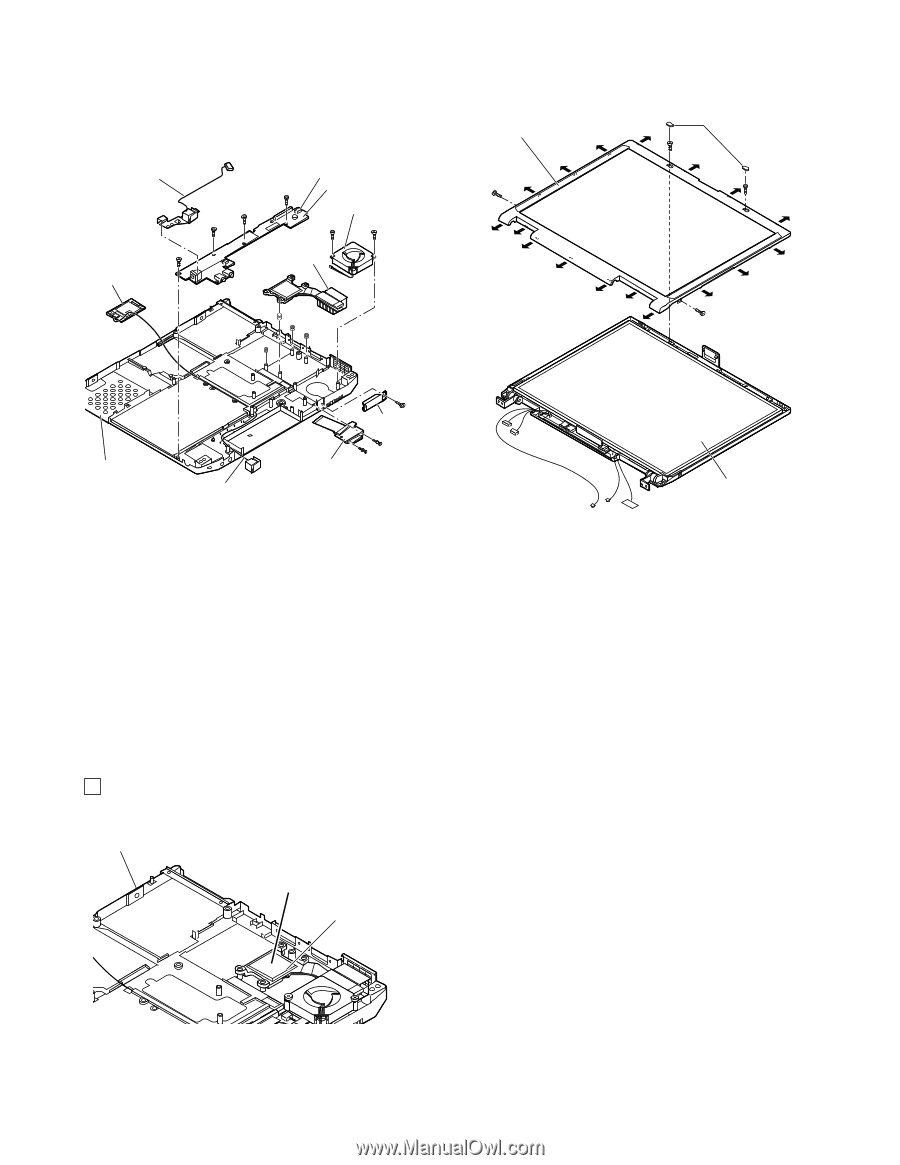
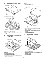
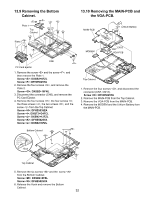
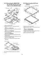
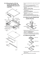
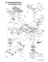
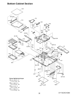
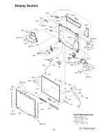
13.11 Removing the REAR-PCB, the I/O-PCB, the Fan, the LAN Cable and the MODEM Cable. LAN Cable CN1005 REAR-PCB Fan MODEM RHE ASSY 13.12 Removing the LCD Front Cabinet. LCD Front Cabinet LCD Rubbers I/O Cover Top Cabinet I/O PCB MODEM Cable 1. Remove the RHE ASSY. 2. Remove the screw , and remove the I/O Cover. Screw : DXSB2+6FZL 3. Remove the two screws , and remove the I/OPCB. Screw : K1YE68000007 4. Remove the four screws , and disconnect the connector (CN1005). Screw : DFHE5025YA 5. Remove the REAR-PCB, the LAN Cable and the MODEM Cable. 6. Remove the two screws , and remove the Fan. Screw : DXQT2+G4FCL ! When you fix, please be sure to apply Grease (pea-size). Bottom Cabinet Thermal Grease RHE Ass'y LCD 1. Remove the two LCD Rubbers. 2. Remove the two screws , and the two screws . Screw : DXQT2+G4FCL Screw : DXQT26+D4FNL 3. Release the seventeen Hooks on the LCD Front Cabinet outward. (See the Figure) 4. Remove the LCD Front Cabinet. G751 Thermal Grease from Shin-Etsu Chemical Co.,Ltd. 33
-
 1
1 -
2
-
3
-
4
-
5
-
6
-
7
-
8
-
9
-
10
-
11
-
12
-
13
-
14
-
15
-
16
-
17
-
18
-
19
-
20
-
21
-
22
-
23
-
24
-
25
-
26
-
27
-
28
-
29
-
30
-
 31
31 -
 32
32 -
 33
33 -
 34
34 -
 35
35 -
 36
36 -
 37
37 -
 38
38 -
 39
39 -
 40
40 -
 41
41 -
42
-
43
-
44
-
45
-
46
-
47
-
48
-
49
-
50
-
51
-
52
-
53
-
54
-
55
-
56
-
57
-
58
-
59
-
60
-
61
-
62
-
63
-
64
-
65
-
66
-
67
-
68
-
69
-
70
-
71
-
72
-
73
-
74
-
75
-
76
-
77
-
78
-
79
-
80
-
81
-
82
-
83
-
84
-
85
-
86
-
87
-
88
-
89
-
90
-
91
-
92
-
93
-
94
-
95
-
96
-
97
-
98
-
99
-
100
-
101
-
102
-
103
-
104
-
105
-
106
-
107
-
108
-
109
-
110
-
111
-
112
-
113
-
114
-
115
-
116
-
117
-
118
 |
 |