Panasonic CF-73SCUTSBM Service Manual - Page 34
Removing the Center Cover., 6 Removing the Keyboard and, the LED-PCB., 7 Removing the LCD Unit.
 |
UPC - 092281843346
View all Panasonic CF-73SCUTSBM manuals
Add to My Manuals
Save this manual to your list of manuals |
Page 34 highlights
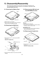
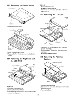
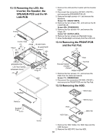
13.5 Removing the Center Cover. Center Cover LED-PCB 1. Remove the screw . Screw : DFHE5025YA 2. Disconnect the connector (CN1300), and remove the LED-PCB. 13.7 Removing the LCD Unit. Hooks 1. Release the three Hooks. Center Cover LCD Unit Hooks CN1001 CN1006 CN801 LCD Unit 2. Open and level the LCD Unit. 3. Release the four Hooks, and remove the Center Cover. 13.6 Removing the Keyboard and the LED-PCB. Keyboard Plate CN802 CN803 Keyboard 1 LED-PCB CN1300 MODULE 1. Disconnect the connectors (CN1001, CN1006, CN801, MODULE). 2. Remove the four screws , and remove the LCD Unit. Screw : DXYN3+J8FZL 13.8 Removing the Palmrest Cabinet. Palmrest Cabinet Hooks Keyboard 1. Turn over the Keyboard.(1) 2. Remove the Keyboard Plate. 3. Disconnect the connectors (CN802, CN803), and remove the Keyboard. Bezel CN19 1. Release the three Hooks. 2. Disconnect the connector (CN19), and remove the Palmrest Cabinet. 3. Remove the Bezel. 31
-
 1
1 -
2
-
3
-
4
-
5
-
6
-
7
-
8
-
9
-
10
-
11
-
12
-
13
-
14
-
15
-
16
-
17
-
18
-
19
-
20
-
21
-
22
-
23
-
24
-
25
-
26
-
27
-
28
-
 29
29 -
 30
30 -
 31
31 -
 32
32 -
 33
33 -
 34
34 -
 35
35 -
 36
36 -
 37
37 -
 38
38 -
 39
39 -
40
-
41
-
42
-
43
-
44
-
45
-
46
-
47
-
48
-
49
-
50
-
51
-
52
-
53
-
54
-
55
-
56
-
57
-
58
-
59
-
60
-
61
-
62
-
63
-
64
-
65
-
66
-
67
-
68
-
69
-
70
-
71
-
72
-
73
-
74
-
75
-
76
-
77
-
78
-
79
-
80
-
81
-
82
-
83
-
84
-
85
-
86
-
87
-
88
-
89
-
90
-
91
-
92
-
93
-
94
-
95
-
96
-
97
-
98
-
99
-
100
-
101
-
102
-
103
-
104
-
105
-
106
-
107
-
108
-
109
-
110
-
111
-
112
-
113
-
114
-
115
-
116
-
117
-
118
 |
 |
