Panasonic CF-73SCUTSBM Service Manual - Page 37
Removing the FRONT-PCB, and the Flat Pad., 15 Removing the HDD., the, Inverter, the Speaker
 |
UPC - 092281843346
View all Panasonic CF-73SCUTSBM manuals
Add to My Manuals
Save this manual to your list of manuals |
Page 37 highlights
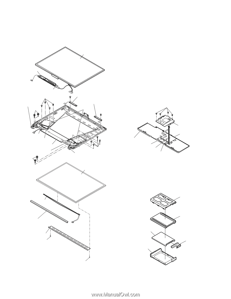
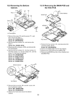
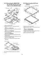
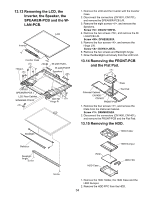
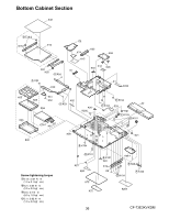
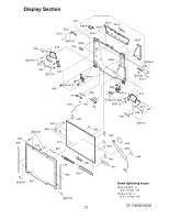
13.13 Removing the LCD, the Inverter, the Speaker, the SPEAKER-PCB and the WLAN-PCB. LCD Inverter Inverter Case Hinge L W-LAN-PCB L W-LAN-PCB R Speakers CN1601 SPEAKER-PCB L LCD Rear Cabinet SPEAKER-PCB R CN1701 Hinge R LCD Backlight 1. Remove the LCD and the Inverter with the Inverter Case. 2. Disconnect the connectors (CN1601, CN1701), and remove the SPEAKER-PCB L/R. 3. Remove the eight screws , and remove the Speakers. Screw : DXQT2+I35FZL 4. Remove the two screws , and remove the WLAN-PCB L/R. Screw : DFHE5025YA 5. Remove the four screws , and remove the Hinge L/R. Screw : DXYN3+J8FZL 6. Remove the two screws and Backlight Angle. 7. Draw the Backlight unit slowly from the LCD Unit. 13.14 Removing the FRONT-PCB and the Flat Pad. Plate Palmrest Cabinet CN1400 CN1401 Flat Pad FRONT-PCB 1. Remove the four screws , and remove the Plate from the Palmrest Cabinet. Screw : DXHM0035ZA 2. Disconnect the connectors (CN1400, CN1401), and remove the FRONT-PCB and the Flat Pad. 13.15 Removing the HDD. HDD Holder Reflector Backlight Angle Screw Screw HDD HDD Case HDD Dumper HDD FPC 1. Remove the HDD Holder, the HDD Case and the HDD Dumper. 2. Remove the HDD FPC from the HDD. 34
-
 1
1 -
2
-
3
-
4
-
5
-
6
-
7
-
8
-
9
-
10
-
11
-
12
-
13
-
14
-
15
-
16
-
17
-
18
-
19
-
20
-
21
-
22
-
23
-
24
-
25
-
26
-
27
-
28
-
29
-
30
-
31
-
 32
32 -
 33
33 -
 34
34 -
 35
35 -
 36
36 -
 37
37 -
 38
38 -
 39
39 -
 40
40 -
 41
41 -
 42
42 -
43
-
44
-
45
-
46
-
47
-
48
-
49
-
50
-
51
-
52
-
53
-
54
-
55
-
56
-
57
-
58
-
59
-
60
-
61
-
62
-
63
-
64
-
65
-
66
-
67
-
68
-
69
-
70
-
71
-
72
-
73
-
74
-
75
-
76
-
77
-
78
-
79
-
80
-
81
-
82
-
83
-
84
-
85
-
86
-
87
-
88
-
89
-
90
-
91
-
92
-
93
-
94
-
95
-
96
-
97
-
98
-
99
-
100
-
101
-
102
-
103
-
104
-
105
-
106
-
107
-
108
-
109
-
110
-
111
-
112
-
113
-
114
-
115
-
116
-
117
-
118
 |
 |