Panasonic FV11VF2 FV11VH2 User Guide - Page 6
Installation, Joist Mounting
 |
View all Panasonic FV11VF2 manuals
Add to My Manuals
Save this manual to your list of manuals |
Page 6 highlights
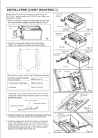
INSTALLATION (JOIST MOUNTING- ) Illustrations in this manual common use the image of FV-11VHL2, and mark for FV-11VHL2 only, others are same for FV-11VH2. 1. Before installation, remove warning lable and the tape that is securing the adapter and the damper. (Fig.1) Suspension bracket Warning label Tape Fan body Suspension bracket Fan body Fig.1 Suspension bracket 2. Insert the suspension bracket into the fan body. (Select the suspension bracket as shown below.) Fan body Suspension Suspension bracket bracket Fig.2-1 Suspension bracket Fig.2-2 Suspension bracket Joists 16 inches and 19.2 inches horizontal joists Fan body Joist Fan body Fig.2-3 Suspension bracket 2 Screw (ST4.2X8) Suspension bracket (Fig.3) 4 Long screws (ST4.2X20) Fig.3 2 Long screws (ST4.2X20) Screw (ST4.2X12) Joist Screw (ST4.2X12) Fig.4-1 16 inches and 19.2 inches horizontal joists refer to Fig.4-1, 19.2 inches vertical joists and 24 inches refer to Fig.4-2. 2 Long screws (ST4.2X20) Joist Fig.4-2
-
 1
1 -
 2
2 -
 3
3 -
 4
4 -
 5
5 -
 6
6 -
 7
7 -
 8
8 -
 9
9 -
 10
10 -
 11
11 -
 12
12
 |
 |
