Panasonic FV11VF2 FV11VH2 User Guide - Page 7
Installation, Joist Mounting, Continued
 |
View all Panasonic FV11VF2 manuals
Add to My Manuals
Save this manual to your list of manuals |
Page 7 highlights
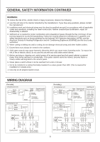
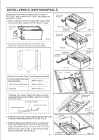
INSTALLATION (JOIST MOUNTING- ) CONTINUED 5. Remove the lighting cord out from hook (FV-11VHL2), then remove junction box plate and secure conduit or stress relief to wiring box knock-out hole.(Fig.5) 6. Refer to wiring diagram (Page.5) Follow all the local electrical safety codes. As well as the National Electrical Code (NEC). Using UL approved wire nuts, connect house power wires to ventilating fan wires (Fig.6): Black to black; white to white; green to green. Make sure all connections are fastened firmly after wiring is finished. Replace the junction box plate, and then replace lighting cord to hook. (Fig.5) Lighting cord Screw driver Junction box plate Hook Screw Fig.5 Black to black Junction box plate White to white Black to black White to white Black to black Green to green Wire nut Black to black White to white Junction box Conduit Fig.6 Conduit Fan body Joist Circular duct Duct tape or clamps 7. Install the circular duct (4 inches) to the adaptor and secure it with duct tape or clamps. (Fig.7) 8. Finish ceiling work. Ceiling hole should be aligned with the edge of the flange. (Fig.8) 9. Install the fluorescent lamps and then install the night lamp. (Fig.8) 4 Long screws (ST4.2X20) 17 3/8 (441) Fig.7 12 5/8 (319) Night lamp Correct Fluorescent lamp Fig.8 Slot Mounting spring 10. Insert mounting springs into slots as shown and mount grille to fan body. (Fig.9) Note:Do not mount grille and springs conversely. If the grille is mounted in the opposite direction, the grille can not be fitted to the ceiling, so then reverse the grille position and try to mount again. Incorrect Grille Switch labels Fig.9 Switch labels (Fig.10) For Model FV-11VHL2 For Model FV-11VH2 Fig.10
-
 1
1 -
 2
2 -
 3
3 -
 4
4 -
 5
5 -
 6
6 -
 7
7 -
 8
8 -
 9
9 -
 10
10 -
 11
11 -
 12
12
 |
 |
