Panasonic SCHTB15 SCHTB15 User Guide - Page 11
Connect the speaker cables., Drive a screw not supplied into the wall.
 |
View all Panasonic SCHTB15 manuals
Add to My Manuals
Save this manual to your list of manuals |
Page 11 highlights
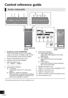
Connect the speaker cables. ≥ To make sure that the speaker cable is connected to the correct speaker, match the color of the speaker connector with the color of the L/R indicator on the speaker label so as not to connect the speaker cable to the wrong speaker. ≥ Insert the wire fully, taking care not to insert beyond the wire insulation. Push 1 Insert the wire fully. r: White s: Blue line 2 Press into the groove. Drive a screw (not supplied) into the wall. ≥ Use the measurements indicated below to identify the screwing positions on the wall. ≥ Leave at least 20 mm (25/32q) of space above and each side of the speaker to allow enough space for fitting the speaker. ≥ The position in the wall where the screw is to be attached as well as the screw should be capable of supporting over 33 kg (72.8 lbs). ≥ Keep the screws out of reach of children to prevent swallowing. A At least 30 mm (13/16q) B ‰4.0 mm (5/32q) C ‰7.0 mm to ‰9.4 mm (9/32q to 3/8q) D Wall or pillar E 5.5 mm to 6.5 mm (7/32q to 1/4q) F 211 mm (85/16q) G 388 mm (159/32q) H 201 mm (729/32q) I 14.3 mm (37/64q) Fit the speaker securely onto the screw(s) with the hole(s). Getting started DO ≥ Move the speaker so that the screw is in this position. DO NOT ≥ In this position, the speaker will likely fall if moved to the left or right. 11 VQT3Q59
-
 1
1 -
2
-
3
-
4
-
5
-
 6
6 -
 7
7 -
 8
8 -
 9
9 -
 10
10 -
 11
11 -
 12
12 -
 13
13 -
 14
14 -
 15
15 -
 16
16 -
17
-
18
-
19
-
20
-
21
-
22
-
23
-
24
-
25
-
26
-
27
-
28
-
29
-
30
-
31
-
32
 |
 |
