Panasonic SVAP10U SVAP10U User Guide - Page 6
Preparation, Controls And Components
 |
View all Panasonic SVAP10U manuals
Add to My Manuals
Save this manual to your list of manuals |
Page 6 highlights
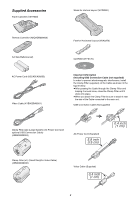
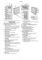
Preparation 78 13 15 16 1 Í 2 PRINT 3 ERROR MENU 4 5 SET 6 DISPLAY/ CANCEL 9 14 10 ACCESS EJECT 11 12 SD MEMORY CARD PC CARD 17 18 19 20 21 VIDEO OUT Preparation Controls and Components 1 Power Lamp [Í] When you turn the power on, the Power lamp turns green. When you turn the power off, the Power lamp turns red, and all images in the Photo Printer's memory are deleted. 2 Power Button [Í] Press to turn Photo Printer on/off. 3 PRINT Button Press this button to print images. 4 MENU Button Use this button to display the menu screen. 5 2134 Buttons/SET Button 2134 Buttons: Use these buttons to select menu choices and card images. SET Button: Use this button to enter various selections. 6 DISPLAY/CANCEL Button DISPLAY Button: Changes the picture display on a card among a Single Screen Display, an Index Display and an Album Display. CANCEL Button: Use to cancel printing and other such processes. Use to exit MENU. 7 Remote Control Receiver Receives the signal from the remote controller. Do not obstruct the remote control receiver in order to avoid difficulties using the remote. 8 Error Lamp Flashes when an error has occurred. 9 Card Access Lamp Lights while the Photo Printer is accessing data on the Card. 10 PC Card Eject Button 11 SD Memory Card/MultiMediaCard Insert Location 12 PC Card Insert Location 13 Paper Cassette Insert Location 14 Stand for Vertical Layout Use the stand for vertical layout. 15 Ink Cassette Eject Lever 16 Ink Cassette Insert Location 17 Power Socket Connects the AC Power Cord (supplied). 18 Paper Removal Port 19 Cord Stopper Fixes the AC Power Cord. 20 USB Socket Connects the USB Connection Cable (not supplied) to the USB Socket for PC. 21 VIDEO OUT Socket Connect the Video Cable (supplied) to Video Input Terminal of TV. 6
-
 1
1 -
 2
2 -
 3
3 -
 4
4 -
 5
5 -
 6
6 -
 7
7 -
 8
8 -
 9
9 -
 10
10 -
 11
11 -
 12
12 -
13
-
14
-
15
-
16
-
17
-
18
-
19
-
20
-
21
-
22
-
23
-
24
-
25
-
26
-
27
-
28
-
29
-
30
-
31
-
32
-
33
-
34
-
35
-
36
-
37
-
38
-
39
-
40
-
41
-
42
-
43
-
44
-
45
-
46
-
47
-
48
-
49
-
50
-
51
-
52
-
53
-
54
-
55
-
56
 |
 |
