Panasonic WJ-PC200 Operating Instructions
Panasonic WJ-PC200 Manual
 |
View all Panasonic WJ-PC200 manuals
Add to My Manuals
Save this manual to your list of manuals |
Panasonic WJ-PC200 manual content summary:
- Panasonic WJ-PC200 | Operating Instructions - Page 1
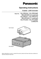
Coaxial - LAN Converter Model No. WJ-PR204 / WJ-PR204E RECEIVER (4-channel) WJ-PR201 / WJ-PR201E RECEIVER (1-channel) WJ-PC200 / WJ-PC200E CAMERA WJ-PC200 WJ-PR204 Before attempting to connect or operate this product, please read these instructions carefully and save this manual for future use. - Panasonic WJ-PC200 | Operating Instructions - Page 2
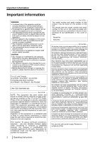
product should be made by qualified service personnel or system installers. • The installation Canada: WJ-PR204 / WJ-PR201 / WJ-PC200 For Europe and other countries: WJ-PR204E / WJ-PR201E / WJ-PC200E in accordance with the instruction manual, may cause harmful interference Panasonic, UP0651S-57PB - Panasonic WJ-PC200 | Operating Instructions - Page 3
information WJ-PR204E/WJ-PR201E . A replacement fuse cover can be purchased from your local Panasonic Dealer. IF THE FITTED MOULDED PLUG IS UNSUITABLE FOR THE and B). Con rm the AC mains plug tted and follow the instructions below. Illustrations may differ from actual AC mains plug. Open the - Panasonic WJ-PC200 | Operating Instructions - Page 4
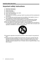
block any ventilation openings. Install in accordance with the manufacturer's instructions. 8. Do not install near any heat sources such as unused for long periods of time. 13. Refer all servicing to qualified service personnel. Servicing is required when the apparatus has been damaged in any - Panasonic WJ-PC200 | Operating Instructions - Page 5
Parts and functions 21 2.1 WJ-PR204/WJ-PR204E/WJ-PR201/WJ-PR201E (connects to the network device) ...21 2.2 WJ-PC200/WJ-PC200E (connects to the 's Firmware 49 Changing coaxial - LAN converter's Settings 50 6 Troubleshooting 51 6.1 Indicator Display Issues 51 6.2 Transmission Speed 52 6.3 - Panasonic WJ-PC200 | Operating Instructions - Page 6
Panasonic supported by all models. PR204 : The functions with these notation are available when using the model WJ-PR204/WJ-PR204E. PR201 : The functions with these notation are available when using the model WJ-PR201/WJ-PR201E PR201 - Panasonic WJ-PC200 | Operating Instructions - Page 7
IEEE802.3at) and PoE+ cameras can be connected and used*1. Use over long distances PR201 The coaxial - LAN converter can be used for distances of up to 300 m ( network cameras recommended by Panasonic, see the Panasonic support site (http://security.panasonic.com/pss/security/support/info.html). *2 - Panasonic WJ-PC200 | Operating Instructions - Page 8
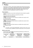
1.2 Introduction About the user manuals • Instruction Manual (this document): Explains the safety precautions, instructions for use and installation, installation and setup procedures, and other information. The external appearance and other parts shown in this manual may differ from the actual - Panasonic WJ-PC200 | Operating Instructions - Page 9
PRODUCT (S). Disclaimer of warranty IN NO EVENT SHALL Panasonic System Networks Co., Ltd. BE LIABLE TO ANY TROUBLE; 4. INCONVENIENCE OR ANY LOSS ARISING WHEN IMAGES ARE NOT DISPLAYED, DUE TO ANY REASON OR CAUSE INCLUDING ANY FAILURE OR PROBLEM OF THE PRODUCT; 5. ANY PROBLEM Instructions 9 - Panasonic WJ-PC200 | Operating Instructions - Page 10
unauthorized external access to the network, we recommend performing the following procedures. - Setup security measures for the router and computers accessing the network. 10 Operating Instructions - Panasonic WJ-PC200 | Operating Instructions - Page 11
included in the unit's packaging. WJ-PR204/WJ-PR204E/WJ-PR201/WJ-PR201E • Operating Instructions (this document) (1 pc.) • Warranty Card (1 pc.) WJ-PR204, WJ-PR201 • AC adapter (1 pc.) • AC Cord (1 pc.) WJ-PR204, WJ-PR201 • AC Cord (2 pcs.)*1 WJ-PR204E, WJ-PR201E • BNC Connector Cover (4 ch.) (1 pc - Panasonic WJ-PC200 | Operating Instructions - Page 12
contact qualified service personnel for service. Select an installation area that can support the the power plug into the power outlet. PR204 PR201 • Failure to do so may cause electric shock any dust, etc. from the power plug. PR204 PR201 • Accumulated dust may cause an insulation defect from - Panasonic WJ-PC200 | Operating Instructions - Page 13
inside the unit. Turn the power off immediately and contact qualified service personnel for service. Only use the included AC adapter. PR204 PR201 • If other AC adapters are used, the voltage and positive/ Failure to observe this may cause an explosion resulting in injury. Operating Instructions 13 - Panasonic WJ-PC200 | Operating Instructions - Page 14
fall of the product may occur. Do not damage the power cable. PR204 PR201 • Do not damage, fabricate, twist, stretch, bundle, or forcibly bend electric shock or fire. Disconnect the power line and contact an authorized service center if there is any damage to the coaxial cables. Do not Instructions - Panasonic WJ-PC200 | Operating Instructions - Page 15
Never touch the power plug with wet hands. PR204 PR201 • This may result in electric shock. Do not pour or wet the unit. • This may result electric shock or fire. Turn the power off immediately and contact qualified service personnel for service. Do not touch the unit, ethernet cable, coaxial cable - Panasonic WJ-PC200 | Operating Instructions - Page 16
this product, nor apply shock or vibration to the product. Failure to observe this may cause trouble. 6. Power cable PR204 PR201 • The attached AC adapter is designed exclusively for this unit. Do not use it for . : Direct current symbol : Alternating current symbol 16 Operating Instructions - Panasonic WJ-PC200 | Operating Instructions - Page 17
not designed for on-vehicle use.) - Locations subject to moisture or dust - Locations subject to condensation as the result of severe changes in temperature Operating Instructions 17 - Panasonic WJ-PC200 | Operating Instructions - Page 18
to the rack, use the following bracket (locally procured). - Rack mount bracket: For WJ-PR204/WJ-PR201: BY-HCA10A For WJ-PR204E/WJ-PR201E: BY-HCA10CE • Available racks - EIA standard rack or equivalent (third party) EIA19 make sure that the anchors and screws are secured. 18 Operating Instructions - Panasonic WJ-PC200 | Operating Instructions - Page 19
) to 0.69 mm (0.027 inches) IMPORTANT • Use a suitable plug. Using a non-specified plug may cause a bad connection or cause damage to the BNC connector. Operating Instructions 19 - Panasonic WJ-PC200 | Operating Instructions - Page 20
product's electrical components or terminals, leading to malfunction. 10. Shielded (STP) LAN cables must be used with this unit to ensure compliance with CE standards. (WJ-PR204E/WJ-PR201E/WJ-PC200E) 11. Make sure to remove this product if it will no longer be used. 20 Operating - Panasonic WJ-PC200 | Operating Instructions - Page 21
to the camera side unit (see page 24). Note The WJ-PR204 is used as an example in some of the illustrations in this document. Rear view WJ-PR201, WJ-PR201E A C A BNC connector Connects the receiver side unit to the power outlet with the included AC cord (see page 39). Operating Instructions 21 - Panasonic WJ-PC200 | Operating Instructions - Page 22
2 Parts and functions WJ-PR204, WJ-PR204E C A BNC connector A Connects the receiver side unit to the camera side unit with a coaxial cable (see page 37). B Network C DC IN Connects the receiver side unit to the power outlet with the included AC cord (see page 39). 22 Operating Instructions - Panasonic WJ-PC200 | Operating Instructions - Page 23
2 Parts and functions 2.2 WJ-PC200/WJ-PC200E (connects to the camera) Front view A LINK Indicator Displays the status of the camera side unit (see A page ). C B Rear view A A Used when attaching the camera side unit to a ceiling or wall with screws (see page 25). Operating Instructions 23 - Panasonic WJ-PC200 | Operating Instructions - Page 24
COAXIAL Red (lit) The receiver side unit is malfunctioning. Contact an authorized service center. Off The receiver side unit is not receiving power, or the side unit is malfunctioning. Contact an authorized service center. The receiver side unit is not operated, or the coaxial cable is - Panasonic WJ-PC200 | Operating Instructions - Page 25
camera side unit. IMPORTANT • Mount the camera side unit to a secure location that is firm enough to support its weight (approximately 110 g (0.24 lb)) and the weight of the cabling. • Mount the camera side (4×20 mm {13/16 inches}) nominal diameter 89 mm {3-1/2 inches} Operating Instructions 25 - Panasonic WJ-PC200 | Operating Instructions - Page 26
±0.22 lbf·ft}) Flat-head (M3×6 mm {1/4 inches}: Rack mount connecting fitting (accessory)) × 12 Underside continuous connecting bracket (Rack mount connecting fitting (accessory)) 26 Operating Instructions - Panasonic WJ-PC200 | Operating Instructions - Page 27
: M3´6 mm {1/4 inches}). When connecting 4 units together, use 1 underside continuous connecting bracket and 16 screws (flat-head: M3´6 mm {1/4 inches}). Keep the remaining parts. Operating Instructions 27 - Panasonic WJ-PC200 | Operating Instructions - Page 28
6 screws (M3´6 mm {1/4 inches}). Use 4 screws (M3´6 mm {1/4 inches}) when mounting to sides of the connected receiver side units. Keep the remaining parts. 28 Operating Instructions - Panasonic WJ-PC200 | Operating Instructions - Page 29
mounting receiver side units to the rack, leave 1U (44 mm {1 23/32 inches}) or more clearance above and below the receiver side units. Operating Instructions 29 - Panasonic WJ-PC200 | Operating Instructions - Page 30
camera Max. 300 m {984 feet}: Cameras recommended by Panasonic*1 AC adaptor PoE Max. 100 m {328 feet} 500 m {1,640 feet}: Cameras recommended by Panasonic*1 External Max. 100 m Max. 100 640 feet}: PoE es} Cameras recommended by Panasonic*1 External Max. 100 m power supply {328 feet - Panasonic WJ-PC200 | Operating Instructions - Page 31
side unit Switching hub *1 For information about network cameras recommended by Panasonic, visit our web site. http://security.panasonic.com/pss/security/support/info.html *2 Use a PoE camera that consumes no more coupler (Included parts of camera side unit) Ethernet cable Operating Instructions 31 - Panasonic WJ-PC200 | Operating Instructions - Page 32
4-27/32 inch es} *1 For information about network cameras recommended by Panasonic, visit our web site. http://security.panasonic.com/pss/security/support/info.html *2 When connecting a PoE camera or PoE+ camera to an is not supplied from camera side unit to the camera. 32 Operating Instructions - Panasonic WJ-PC200 | Operating Instructions - Page 33
is reconnected too quickly, power may not be supplied form the PoE power supply. • Some crossover-type Ethernet cables cannot supply power using PoE. Operating Instructions 33 - Panasonic WJ-PC200 | Operating Instructions - Page 34
Camera Ethernet cable Network connector • When using an external power supply to supply power to a PoE or PoE+ camera, refer to page 31. 34 Operating Instructions - Panasonic WJ-PC200 | Operating Instructions - Page 35
value: 1 MW or more for DC 500 V • Confirm the length of the coaxial cable when using the PoE function (see page 30, page 32). Operating Instructions 35 - Panasonic WJ-PC200 | Operating Instructions - Page 36
cables are connected to ch2, ch3, and ch4 terminals. When removing the BNC connector cover cap (accessory), rotate it slightly to the left. 36 Operating Instructions - Panasonic WJ-PC200 | Operating Instructions - Page 37
illustrations below show an example to establish the 2-channel connection to a 4-channel unit model. The procedure is the same as for a 1-channel unit model. Operating Instructions 37 - Panasonic WJ-PC200 | Operating Instructions - Page 38
-5e or higher) to the receiver side unit and network or PoE power supply device. Network connector Network device Ethernet cable Network connector 38 Operating Instructions - Panasonic WJ-PC200 | Operating Instructions - Page 39
and the receiver side units. LINK indicator (Green) POWER indicator (Green) LAN indicator (Green) COAXIAL indicator (Green) • If the indicator does not light correctly, see "Troubleshooting" on page 51. Operating Instructions 39 - Panasonic WJ-PC200 | Operating Instructions - Page 40
default IP address of the camera is "192.168.0.10"> Address to enter: "http://192.168.0.10/" • For the PC settings, see the camera's Operating Instructions. 40 Operating - Panasonic WJ-PC200 | Operating Instructions - Page 41
values. • If you plan to update the adapter's firmware, download the latest version of the coaxial - LAN converter's firmware from the Panasonic support site (http://security.panasonic.com/pss/security/support/) and save it on the computer before you change the IP address of the computer. Operating - Panasonic WJ-PC200 | Operating Instructions - Page 42
[View your active networks]®[Local Area Connection]. 3. Click [Properties] under [Local Area Connection Status]. 4. Select [Internet Protocol Version 4 (TCP/IPv4)], then click [Properties]. 42 Operating Instructions - Panasonic WJ-PC200 | Operating Instructions - Page 43
method or Windows 7 is set to [Large icons] or [Small icons]. Refer to the help file supplied with the operating system for more information. Operating Instructions 43 - Panasonic WJ-PC200 | Operating Instructions - Page 44
. - Default user name: Model no. - Default password: 999999 • The screen shown here depicts the screen shown when using Windows 7. Model no. WJ-PR204/WJ-PR204E WJ-PR201/WJ-PR201E WJ-PC200/WJ-PC200E User name WJ-PR204 WJ-PR201 WJ-PC200 44 Operating Instructions Password 999999 999999 999999 - Panasonic WJ-PC200 | Operating Instructions - Page 45
LAN converter 5. Click [OK]. • The maintenance screen is displayed. Receiver side unit WJ-PR204 Camera side unit WJ-PC200 IMPORTANT • Only a PC connected to the coaxial - LAN converter's network connector Master" are only displayed on the screen of the camera side unit. Operating Instructions 45 - Panasonic WJ-PC200 | Operating Instructions - Page 46
screen. You may reset the computer's ARP table if you do not want to restart the computer. Refer to the help file or operating instructions included with the operating system for more information. Resetting the ARP table when using Windows 7 1. Display the command prompt by clicking [Start]®[All - Panasonic WJ-PC200 | Operating Instructions - Page 47
] screen. 1. Access the maintenance screen of the coaxial - LAN converter. 2. Click [Status]. WJ-PR204 The screen shown above is the maintenance screen of the receiver side unit. IMPORTANT • The performance may be affected if other receiver side units are detected. Operating Instructions 47 - Panasonic WJ-PC200 | Operating Instructions - Page 48
connection. MAC address of the Master (only displayed for the camera side unit) Displays the MAC address of the connected receiver side unit. 48 Operating Instructions - Panasonic WJ-PC200 | Operating Instructions - Page 49
PC before changing the IP address of the PC. You can download the firmware from the Panasonic support site (http://panasonic.net/pss/security/products/coax/index.html). • Update the firmware for both the camera side 's firmware version on the [Status] screen (see page 47). Operating Instructions 49 - Panasonic WJ-PC200 | Operating Instructions - Page 50
's maintenance screen again. 7. Click [Restart], then click [Reset] button in the restart tab. WJ-PR204 After restarting, make connections using the changed IP address displayed in the maintenance screen. IMPORTANT • the new IP address and keep a note for future reference. 50 Operating Instructions - Panasonic WJ-PC200 | Operating Instructions - Page 51
problem can be resolved by following the troubleshooting steps. If the problem cannot be solved by the steps in the troubleshooting, contact an authorized service center. 6.1 Indicator Display Issues Problem problems such as damage or breaks in the cable (see page 38). Operating Instructions 51 - Panasonic WJ-PC200 | Operating Instructions - Page 52
6 Troubleshooting Problem The receiver side unit's • COAXIAL indicator is not the receiver side unit may be malfunctioning. → Contact an authorized service center. 6.2 Transmission Speed Problem The LINK indicator of camera side goes off, or transmission is is emitted. 52 Operating Instructions - Panasonic WJ-PC200 | Operating Instructions - Page 53
Troubleshooting 6.3 PoE+/PoE Issues Problem cable (see page 30, 32), and that there are no connection problems such as damage or breaks in the cable. The combination of reconnect after waiting for more than 2 seconds. 6.4 Other Issues Problem The AC adapter is warm. Cause and Remedy • This is - Panasonic WJ-PC200 | Operating Instructions - Page 54
the included AC adapter. • DC 57 V/ 700 mA/ Approx. 40 W PR201 • DC 57 V/ 1.14 A/ Approx. 65 W PR204 Use the PoE 10Base-T/100Base-TX ´ 1 BNC connector ´ 1 PR201 BNC connector ´ 4 PR204 Dimensions (W´H´D) Width: approx Weight) About 250 g (0.55 lb) PR201 About 270 g (0.60 lb) PR204 Finish Main unit: - Panasonic WJ-PC200 | Operating Instructions - Page 55
Coaxial Interface Items Standard Frequency Range Data Transfer Mode Access Method Error Correction Specifications Panasonic original system 2 MHz-28 MHz Wavelet OFDM CSMA/CA Reed-Solomon Code + Straight cable automatic recognition 10 Mbps/100 Mbps (Auto-Sensing) Operating Instructions 55 - Panasonic WJ-PC200 | Operating Instructions - Page 56
be connected.*1 PR204 One camera side unit can be connected. PR201 Connectable Devices Receiver side unit: devices equipped with 10Base-T/ 100Base-TX the cameras specified by Panasonic, visit our website: http://security.panasonic.com/pss/security/support/info.html *2 The Operating Instructions - Panasonic WJ-PC200 | Operating Instructions - Page 57
website: http://security.panasonic.com/pss/security/support/info.html *4 The maximum length of an Ethernet cable used to connect a PoE+ camera is 50 m (164 feet). Accessories Rack Mount Connecting Fitting - BY-HCA10A: WJ-PR204, WJ-PR201 - BY-HCA10CE: WJ-PR204E, WJ-PR201E Operating Instructions 57 - Panasonic WJ-PC200 | Operating Instructions - Page 58
Notes 58 Operating Instructions - Panasonic WJ-PC200 | Operating Instructions - Page 59
Notes Operating Instructions 59 - Panasonic WJ-PC200 | Operating Instructions - Page 60
of this waste, in accordance with national legislation. For U.S. and Canada: Panasonic System Communications Company of North America, Unit of Panasonic Corporation of North America www.panasonic.com/business/ For customer support, call 1.800.528.6747 Two Riverfront Plaza, Newark, NJ 07102-5490
-
 1
1 -
 2
2 -
 3
3 -
 4
4 -
 5
5 -
 6
6 -
 7
7 -
8
-
9
-
10
-
11
-
12
-
13
-
14
-
15
-
16
-
17
-
18
-
19
-
20
-
21
-
22
-
23
-
24
-
25
-
26
-
27
-
28
-
29
-
30
-
31
-
32
-
33
-
34
-
35
-
36
-
37
-
38
-
39
-
40
-
41
-
42
-
43
-
44
-
45
-
46
-
47
-
48
-
49
-
50
-
51
-
52
-
53
-
54
-
55
-
56
-
57
-
58
-
59
-
60
 |
 |

Operating Instructions
Coaxial - LAN Converter
Model No.
WJ-PR204 / WJ-PR204E
RECEIVER (4-channel)
WJ-PR201 / WJ-PR201E
RECEIVER (1-channel)
WJ-PC200 / WJ-PC200E
CAMERA
WJ-PC200
WJ-PR204
Before attempting to connect or operate this product, please read these instructions carefully and
save this manual for future use.