Panasonic fv08vsl1 Installation Instructions - Page 11
ST4.2X20.
 |
View all Panasonic fv08vsl1 manuals
Add to My Manuals
Save this manual to your list of manuals |
Page 11 highlights
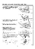
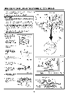
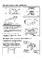
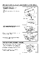
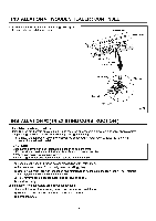
INSTALLATION IV ( BETWEEN JOIST MOUNTING ) CONTINUED 3. Insert the fan body between joists. Make sure the fan body is level and square (perpendicular) with the joists. (Fig.17) CAUTION: Backside of flange should mount directly to bottom of joist. Joists Adaptor 4. Secure the suspension bracket to joists by using long screws (ST4.2X20). (Fig.18, Fig.19) Fan body Junction box Suspension bracket T\ 13 1/4-151/2 (336-394) 16 1/2-183/4 (419-480) 21 1/4-2312 ( 540-597 ) B Il l Unit: inches (mm) Fig.17 2 Long screws (ST4.2X20) Joist 5. Secure the suspension bracket to fan body by using screw If (ST4.2X12). (Fig.19) 2 Screw II (ST4.2X12) 4 Long screws (ST4.2)(20) Fig.18 6. Follow step 5 to 11 of installation I (page 7-page 8) to complete the installation work. INSTALLATION V ( WOODEN HEADER ) 1. Before installation, secure the fan body to adaptor by using thumb screw (Fig.13 of page 10). Secure the lighting unit to fan body (refering to Fig.6 of page 8). 2. Install header between joists by using nails or screws. 3. Install the fan body and secure it by using long screws (ST4.2X20). (Fig.20, Fig.21) Joist (370s7) Fan body Unit: inches (mm) 11 Joist Fig.19 Header Joist Adaptor Fig.20
-
 1
1 -
2
-
3
-
4
-
5
-
 6
6 -
 7
7 -
 8
8 -
 9
9 -
 10
10 -
 11
11 -
 12
12 -
 13
13 -
 14
14
 |
 |
