Panasonic fv08vsl1 Installation Instructions - Page 5
General, Safety, Information, Continued, Wiring, Diagram
 |
View all Panasonic fv08vsl1 manuals
Add to My Manuals
Save this manual to your list of manuals |
Page 5 highlights
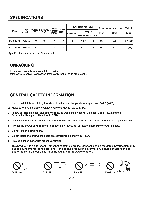
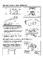
GENERAL SAFETY INFORMATION CONTINUED CAUTION: 1. For general ventilating use only. Do not use to exhaust hazardous or explosive materials and vapors. 2. Not for use in cooking area. (Fig .B) 3. This product must be properly grounded. (Cooking area) Do not install above or •• inside this area • 4r6", Cooking equipment Fig. B Floor WARNING: To reduce the risk of fire, electric shock or injury to persons, observe the following: 1. Use this unit only in the manner intended by the manufacturer. If you have any questions, contact to the manufacturer. 2. Installation work and electrical wiring must be done by qualified person(s) in accordance with all applicable codes and standards, including fire-rated construction. 3. Sufficient air is needed for proper combustion and exhausting of gases through the flue (chimney) of fuel burning equipment to prevent backdrafting. Follow the heating equipment manufacturer's guideline and safety standards such as those published by the National Fire Protection Association (NFPA), and the American Society for Heating Refrigeration and Air Conditioning Engineers (ASHRAE) and the local code authorities. 4. When cutting or drilling into wall or ceiling, do not damage electrical wiring and other hidden utilities. 5. Ducted fans must always be vented to the outdoors. 6. These models are UL listed for tub and shower enclosures. 7. Solid state controls may cause harmonic distortion which can cause motor humming noise. To reduce the risk of fire or electric shock, do not use this unit with any solid-state control device. 8. Before servicing or cleaning unit, switch power off at service panel and lock the service disconnecting means to prevent power from being switched on accidentally. When the service disconnecting means cannot be locked, securely fasten a prominent warning device, such as a tag, to the service panel. 9. If this unit is to be installed over a tub or shower, it must be marked as appropriate for the application and be connected to a GFCI (Ground Fault Circuit Interrupter) - protected branch circuit. 10. NEVER place a switch where it can be reached from a tub or shower. 11. Not to be installed in a ceiling thermally insulated to a value greater than R40. (This is required for installation in Canada only.) WIRING DIAGRAM FV-08VSL1 Current Fuse 3.15A Electronic Ballast Fluorescent lamp FV-10VSL1 Current Fuse 3.15A Electronic Ballast Fluorescent lamp Fan body Black White Motor Red 1 Capacitor WhIteT Black •Green White Green Night lamp Earth ground • I Black • ,I White Lighting unit .I"r4 BWlaI.ck I Live White Neutral Black I Live Green I Earth Junction box - I Black White lI Power Supply AC120V 60Hz > Power Supply > AC120V 60Hz 5 Night lamp Fan body Motor Thermally protected Red Capacitor WhiteT Black reen Earth ground .Black Lighting nit Black I Live • White White White Black White I Neutral Black I Live White n. Black l l l Green I II White I Neutral Black I Live Green Earth I Junction box Power Supply AC120V 60Hz Power Supply AC120V 60Hz
-
 1
1 -
 2
2 -
 3
3 -
 4
4 -
 5
5 -
 6
6 -
 7
7 -
 8
8 -
 9
9 -
 10
10 -
 11
11 -
12
-
13
-
14
 |
 |
