Philips FWM70 User manual - Page 13
Step 1, Connecting FM/AM, antennas, Step 2, Connecting the speakers, Step 3, Connecting to the game
 |
View all Philips FWM70 manuals
Add to My Manuals
Save this manual to your list of manuals |
Page 13 highlights
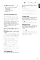
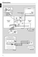
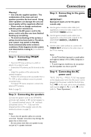
English Connections Warning! - Use only the supplied speakers. The combination of the main unit and speakers provides the best sound. Using other speakers can damage the unit and sound quality will be negatively affected. - Never make or change connections with the power switched on. - Connect the AC power cord to the power outlet only after you have finished hooking up everything. - To avoid overheating of the system, a safety circuit has been built in.Therefore, your system may switch to Standby mode automatically under extreme conditions. If this happens, let the system cool down before reusing it (not available for all versions). Step 1: Connecting FM/AM antennas - Place the AM loop antenna on a shelf or attach it to a stand or wall. - Extend the FM antenna and fix its ends to the wall. - Adjust the position of the antennas for optimal reception. - Position the antennas as far as possible from a TV, VCR or other radiation source to prevent unwanted noise. - For better FM stereo reception, connect the external FM antenna. Refer to page 12. Step 3: Connecting to the game console IMPORTANT! Gameport inputs are for the game console only. a. Use the game console's video cable (not supplied) to connect its video output to the GAMEPORT-VIDEO terminal. b. Use the game console's audio cables (not supplied) to connect its audio outputs to the GAMEPORT-AUDIO L. / AUDIO R. terminals. c. Use the video cable (yellow) to connect the VIDEO OUT terminal to the video input on the TV for viewing. Notes: - On the TV, the Video Input jack is usually yellow and might be labeled A/V In, CVBS, Composite or Baseband. - To avoid magnetic interference, do not position the front speakers too close to your TV. Step 4: Connecting the AC power cord "AUTO INSTALL - PRESS PLAY" may appear on the display panel when the AC power cord is plugged into the power outlet for the first time. Press ÉÅ on the main unit to store all available radio stations (page 3 - P3) or press Ç to exit (refer to "Tuner Operations"). Step 2: Connecting the speakers Connect the speaker wires to the SPEAKERS terminals, right speaker to "R" and left speaker to "L", coloured (marked) wire to "+" and black (unmarked) wire to "-". Fully insert the stripped portion of the speaker wire into the terminal as shown on page 12. Notes: - Ensure that the speaker cables are correctly connected. Improper connections may damage the system due to short-circuit. - Do not connect more than one speaker to any one pair of +/- speaker terminals. 13
-
 1
1 -
2
-
3
-
4
-
5
-
6
-
7
-
 8
8 -
 9
9 -
 10
10 -
 11
11 -
 12
12 -
 13
13 -
 14
14 -
 15
15 -
 16
16 -
 17
17 -
 18
18 -
19
-
20
-
21
-
22
-
23
-
24
-
25
-
26
-
27
-
28
 |
 |