Pioneer KEH-P2030 Service Manual - Page 20
Pcb Connection Diagram
 |
View all Pioneer KEH-P2030 manuals
Add to My Manuals
Save this manual to your list of manuals |
Page 20 highlights
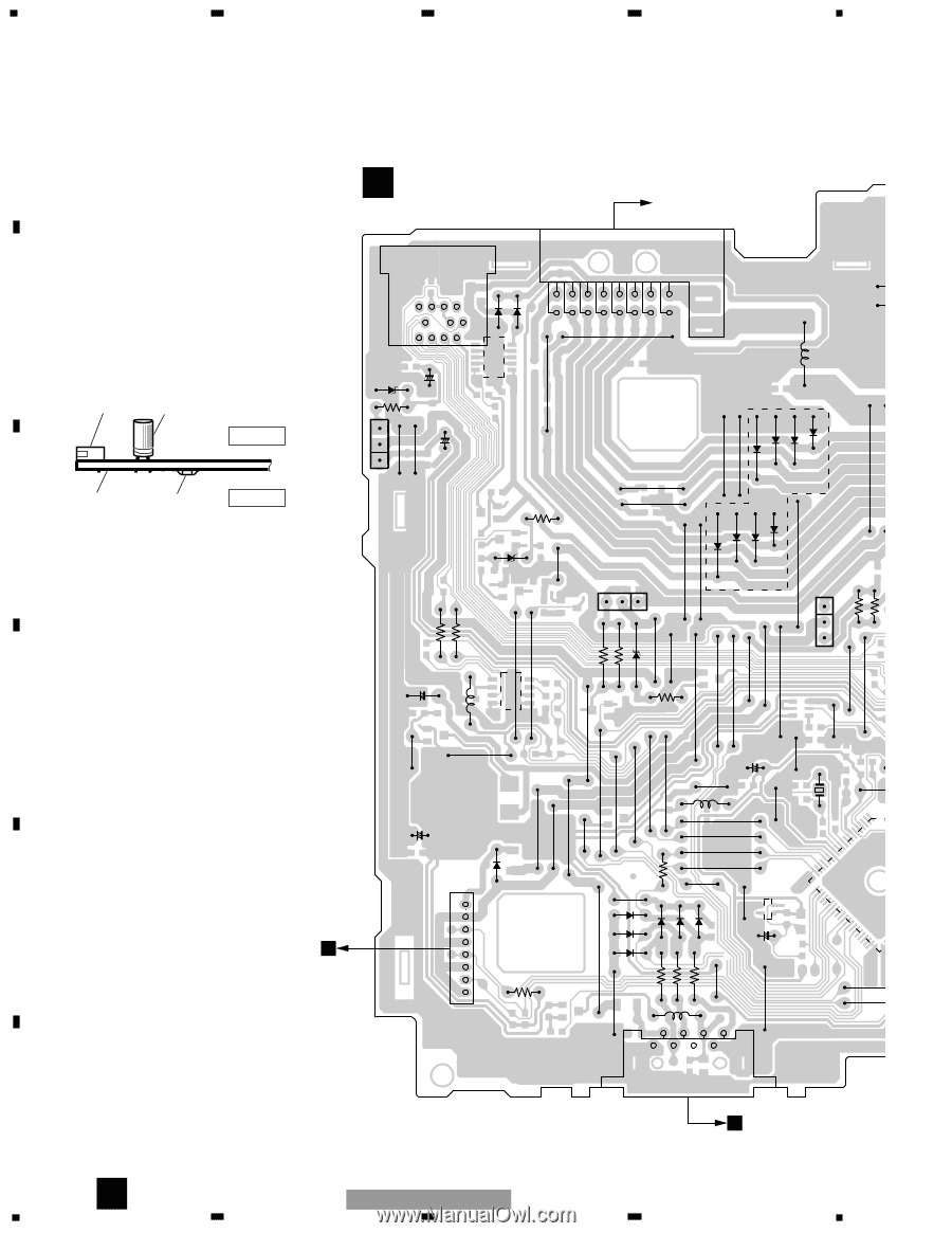
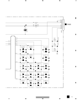
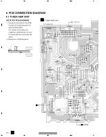
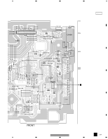
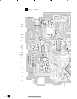
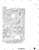
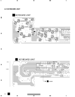
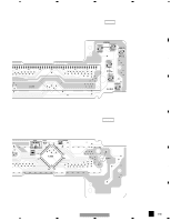
1 2 3 4 A 4. PCB CONNECTION DIAGRAM 4.1 TUNER AMP UNIT NOTE FOR PCB DIAGRAMS 1. The parts mounted on this PCB include all necessary parts for several destination. For further information for respective destinations, be sure to check with the schematic diaB gram. 2. Viewpoint of PCB diagrams A TUNER AMP UNIT BUS CONNECTOR CN400 CORD ASSY CN600 17 4 3 21 16 15 14 13 12 11 10 9 7 65 D604 8765 43 2 1 18 11 10 9 8 D605 D608 + C612 Connector Capacitor R610 D600 D601 L600 (ES) SIDE A P.C.Board Chip Part SIDE B C E Q604 + C609 R604 D603 R408 R406 D602 Q606 E R616 D508 D504 D506 D502 D503 D507 D505 D509 Q250 E R252 R253 R615 C608 + L400 D609 R612 D D607 C3 + X1 L1 C605 + D250 R9 1 D804 D802 D801 E 2 D800 3 D803 C4 C 4 5 + D805 R801 R800 6 7 R256 8 R802 CN250 L800 7531 8642 CN800 F B CN900 A 20 KEH-P2030/XM/UC 1 2 3 4
-
 1
1 -
2
-
3
-
4
-
5
-
6
-
7
-
8
-
9
-
10
-
11
-
12
-
13
-
14
-
 15
15 -
 16
16 -
 17
17 -
 18
18 -
 19
19 -
 20
20 -
 21
21 -
 22
22 -
 23
23 -
 24
24 -
 25
25 -
26
-
27
-
28
-
29
-
30
-
31
-
32
-
33
-
34
-
35
-
36
-
37
-
38
-
39
-
40
-
41
-
42
-
43
-
44
 |
 |