Pioneer KEH-P2030 Service Manual - Page 39
Operational Flow Chart
 |
View all Pioneer KEH-P2030 manuals
Add to My Manuals
Save this manual to your list of manuals |
Page 39 highlights
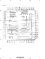
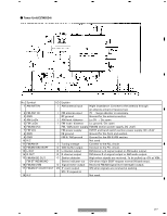
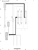
5 6 7 8 7.3 OPERATIONAL FLOW CHART A Backup, Acc ON VDD=5V Pin 68/74 B BSENS Pin 66 BSENS=L ASENS Pin 65 ASENS=L C DSENS Pin 63 IPPW ASENBO DSENS=L H Pin 59 H Pin 58 Starts communication with Grille 300ms D microcomputer. SWVDD L Pin 39 SOURCE key ON TUNER ON 300ms In case of the above signal, the communication with Grille microcomputer may fail. If the time interval is not 300msec, the oscillator may be defective. E SYSPW H Pin 54 Completes power-on operation. F (After that, proceed to each source operation.) KEH-P2030/XM/UC 39 5 6 7 8
-
 1
1 -
2
-
3
-
4
-
5
-
6
-
7
-
8
-
9
-
10
-
11
-
12
-
13
-
14
-
15
-
16
-
17
-
18
-
19
-
20
-
21
-
22
-
23
-
24
-
25
-
26
-
27
-
28
-
29
-
30
-
31
-
32
-
33
-
 34
34 -
 35
35 -
 36
36 -
 37
37 -
 38
38 -
 39
39 -
 40
40 -
 41
41 -
 42
42 -
 43
43 -
 44
44
 |
 |

39
5
6
7
8
F
E
D
C
B
A
5
6
7
8
KEH-P2030/XM/UC
DSENS=L
Backup, Acc ON
VDD=5V
Pin 68/74
BSENS
Pin 66
ASENS
Pin 65
DSENS
Pin 63
SOURCE key
ON
SWVDD
L
Pin 39
TUNER
ON
SYSPW
H
Pin 54
BSENS=L
ASENS=L
300ms
300ms
In case of the above signal, the communication
with Grille microcomputer may fail.
If the time interval is not 300msec, the oscillator
may be defective.
Completes power-on operation.
(After that, proceed to each source operation.)
IPPW
H
Pin 59
ASENBO
H Pin 58
Starts communication
with Grille
microcomputer.
7.3 OPERATIONAL FLOW CHART