Pioneer KEH-P2030 Service Manual - Page 44
Connection Diagram - cable
 |
View all Pioneer KEH-P2030 manuals
Add to My Manuals
Save this manual to your list of manuals |
Page 44 highlights
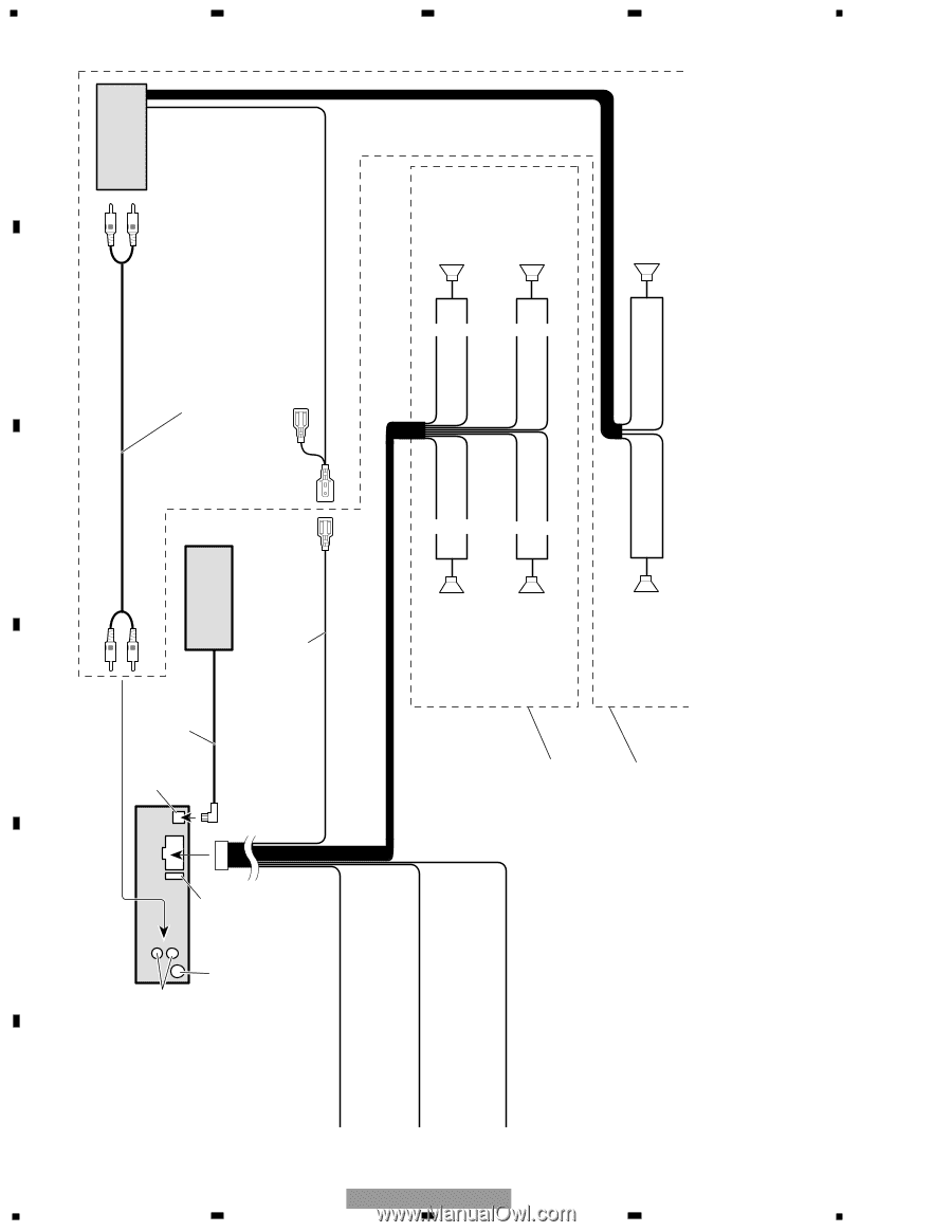
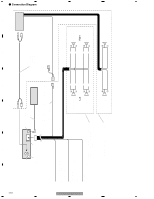
A B C D E F 1 - Connection Diagram 44 1 2 2 Rear output This Product Fuse Antenna jack IP-BUS input (Blue) IP-BUS cable Multi-CD player (sold separately) Connecting cords with RCA pin plugs (sold separately) Power amp (sold separately) Blue/white To system control terminal of the power amp or Auto-antenna relay control terminal (max. 300 mA 12 V DC). Yellow To terminal always supplied with power regardless of ignition switch position. Red To electric terminal controlled by ignition switch (12 V DC) ON/OFF. Black (ground) To vehicle (metal) body. With a 2 speaker system, do not connect anything to the speaker leads that are not connected to speakers. System remote control + Front speaker ≠ Left + Rear speaker ≠ White White/black Green Green/black Gray Gray/black Violet Violet/black + Front speaker ≠ Right + Rear speaker ≠ KEH-P2030/XM/UC 3 3 Perform these connections when using the optional amplifier. + Rear speaker ≠ + Rear speaker ≠ 4 4
-
 1
1 -
2
-
3
-
4
-
5
-
6
-
7
-
8
-
9
-
10
-
11
-
12
-
13
-
14
-
15
-
16
-
17
-
18
-
19
-
20
-
21
-
22
-
23
-
24
-
25
-
26
-
27
-
28
-
29
-
30
-
31
-
32
-
33
-
34
-
35
-
36
-
37
-
38
-
 39
39 -
 40
40 -
 41
41 -
 42
42 -
 43
43 -
 44
44
 |
 |