Pioneer KEH-P2030 Service Manual - Page 37
Tuner UnitCZW5534
 |
View all Pioneer KEH-P2030 manuals
Add to My Manuals
Save this manual to your list of manuals |
Page 37 highlights
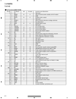
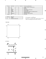
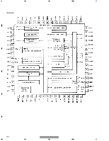
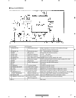
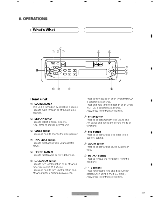
5 6 7 8 - Tuner Unit(CZW5534) A B C No. Symbol I/O Explain 1 AM ANT IN I AM antenna input Hight impedance. Connect to the antenna through an antenna circuit of receiver set. 2 FM ANT IN I FM antenna input 75Ω . Surge absober is necessary. 3 GND RF ground Ground for the antenna section. 4 AM Lo/Dx I AM local /distance Lo: 5V / Dx: open 5 FM Lo/Dx I FM local / distance Lo: ground / Dx: open 6 FM/AM VCC FM / AM power supply FM/AM section power supply. DC +8.2V D 7 FM VCC FM power supply FM RF and band switch section power supply. DC +8.2V 8 GND FE ground Ground for the front end section. 9 GND FM IF/ AM ground Ground for the FM IF/AM section. 10 N.C Not used. 11 FM/AM Vt I Tuning voltage Connect to the PLL circuit. 12 FM/AM OSC BUFF O OSC buffer output Connect to the PLL circuit. 13 L OUT O L channel output FM stereo L-ch signal output or AM audio output. 14 R OUT O R channel output FM stereo R-ch signal output or AM audio output. 15 FM/AM SD OUT O Station detector High when signals are received. To be pulled up +5V at 100kΩ FM ST IND/MONO Stereo indicator out ON when 16pin SD/IF request normal 0V(seek stop). E 16 FM/AM VSM O Signal meter output Received FM/AM signal level (strength) output. 17 FM/AM IF COUNT OUT I/O IF count output ON when signals are received at seeking. SD / IF request in 18 N.C Not used. F KEH-P2030/XM/UC 37 5 6 7 8
-
 1
1 -
2
-
3
-
4
-
5
-
6
-
7
-
8
-
9
-
10
-
11
-
12
-
13
-
14
-
15
-
16
-
17
-
18
-
19
-
20
-
21
-
22
-
23
-
24
-
25
-
26
-
27
-
28
-
29
-
30
-
31
-
 32
32 -
 33
33 -
 34
34 -
 35
35 -
 36
36 -
 37
37 -
 38
38 -
 39
39 -
 40
40 -
 41
41 -
 42
42 -
43
-
44
 |
 |
