Pioneer PRO-930HD Owner's Manual - Page 71
Connecting other audio equipment
 |
View all Pioneer PRO-930HD manuals
Add to My Manuals
Save this manual to your list of manuals |
Page 71 highlights
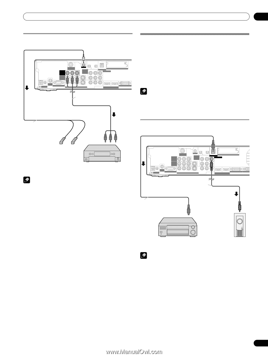
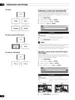
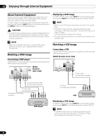
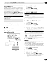
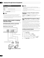
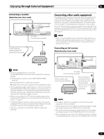
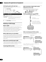
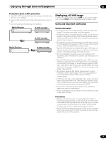
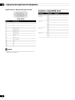
Enjoying through External Equipment 12 Connecting a recorder Media Receiver (rear view) MONITOR OUT ANT/ CABLE A IN INPUT 2 G-LINK INPUT 3 S400 (TS) R-AUDIO-L OPTICAL DIGITAL OUT SUB WOOFER Cable CARD I N OUT CONTROL ANT B IN SERVICE ONLY R-AUDIO-L VIDEO S-VIDEO INPUT 1 Y CB / PB COMPONENT VIDEO CR / PR INPUT 1 INPUT 3 HDMI BLACK SYSTEM AV cable (commercially available) Connecting other audio equipment The digital audio output terminal (optical) on this system can output Dolby Digital signals. Using an optical digital cable, connect an AV receiver to the digital audio output terminal (optical) on the rear of the Media Receiver. This allows audio such as digital TV broadcasting to be played in high quality. If your AV receiver does not have a digital audio input terminal (optical), connect the MONITOR OUT terminals (AUDIO) on the rear of the Media Receiver to the audio input terminals on the AV receiver. NOTE • When using the digital audio output terminal (optical), you need to make settings depending on your AV receiver. For more information, see the instruction manual that came with the AV receiver. G-LINK cable (for presetting digital TV programs for recording) Connecting an AV receiver Media Receiver (rear view) VCR NOTE • About the MONITOR OUT terminals The MONITOR OUT terminals cannot output the following signals: 1 Video signals input from the COMPONENT VIDEO terminal 2 Video signals from a personal computer 3 Digital video and audio signals from the HDMI terminals • When watching images played back on a VCR connected to the MONITOR OUT terminals, select an input source (e.g., TV channel reception) on the recording equipment other than external input sources. Selecting an external input source may result in distorted images or noise. • Make sure to place the VCR into the standby status when presetting TV programs for recording with the TV Guide On Screen™ system. • If degraded picture quality is observed while viewing copyprotected VOD movies connect the Media Receiver directly to other TV sets. Do not connect through a VCR. • Use only one wand on the G-LINK cable to control the recorder. MONITOR OUT ANT/ CABLE A IN INPUT 2 G-LINK INPUT 3 S400 (TS) R-AUDIO-L OPTICAL DIGITAL OUT SUB WOOFER Cable CARD I N OUT CONTROL ANT B IN SERVICE ONLY R-AUDIO-L VIDEO S-VIDEO INPUT 1 Y CB / PB COMPONENT VIDEO CR / PR INPUT 1 INPUT 3 HDMI BLACK WH SYSTEM CABLE AV cable (commercially available) Optical digital cable (commercially available) This connection is not required when connecting an AV amp equipped with the surround function to a subwoofer. AV receiver Subwoofer NOTE • For details, refer to the operation manual for the audio equipment to be connected. • Audio signals synchronizing with currently displayed images are always output to the MONITOR OUT terminals. • The audio accompanying the images shown on the display are always output to the SUBWOOFER OUTPUT terminal. • When signals are input from the HDMI terminals, no digital or analog signals are output from the DIGITAL OUT terminal. 71 En
-
 1
1 -
2
-
3
-
4
-
5
-
6
-
7
-
8
-
9
-
10
-
11
-
12
-
13
-
14
-
15
-
16
-
17
-
18
-
19
-
20
-
21
-
22
-
23
-
24
-
25
-
26
-
27
-
28
-
29
-
30
-
31
-
32
-
33
-
34
-
35
-
36
-
37
-
38
-
39
-
40
-
41
-
42
-
43
-
44
-
45
-
46
-
47
-
48
-
49
-
50
-
51
-
52
-
53
-
54
-
55
-
56
-
57
-
58
-
59
-
60
-
61
-
62
-
63
-
64
-
65
-
 66
66 -
 67
67 -
 68
68 -
 69
69 -
 70
70 -
 71
71 -
 72
72 -
 73
73 -
 74
74 -
 75
75 -
 76
76 -
77
-
78
-
79
-
80
-
81
-
82
-
83
-
84
-
85
-
86
-
87
-
88
-
89
-
90
-
91
-
92
-
93
-
94
-
95
-
96
-
97
-
98
-
99
-
100
 |
 |