Poulan 532430614 User Manual - Page 3
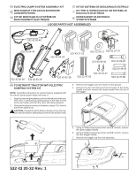
Assembly Instructions For Tractors, Factory Equipped With Electric Dump, System Begin Here.
 |
View all Poulan 532430614 manuals
Add to My Manuals
Save this manual to your list of manuals |
Page 3 highlights
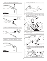
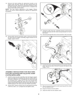
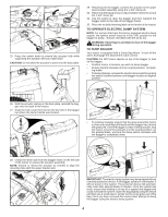
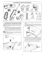
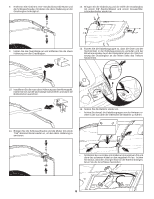
15. Remove the bolts holding the adjustment bracket to the support tube and then remove the pivot bracket from the adjustment bracket. Replace the adjustment bracket (A) with the high strength version included in the kit. Complete this step on both sides of the tractor. NOTE: This may require adjustment of the bagger. Please refer to the tractor Owner's/Operator's Manual for adjustment procedures. A 16. Using a 9/16" wrench and 9/16" socket, remove the bolt and nut that holds the bagger assembly support bracket to the bagger support frame. 19. Using the 2-3/8" clevis pin, install the actuator onto the lower bracket assembly with the motor facing towards the front of the tractor. 20. Push a clip through the hole on the end of the 2-3/8" clevis pin. 21. Connect the wire connectors between the actuator and harness. Use the zip ties in the kit to secure the wires to the bagger frame. ASSEMBLY INSTRUCTIONS FOR TRACTORS FACTORY EQUIPPED WITH ELECTRIC DUMP SYSTEM BEGIN HERE. 17. Install the lower bracket assembly onto the bagger support frame and align the mounting hole with the current hole in the frame. Install the 2 1/2" carriage bolt from the kit through the mounting hole, making sure to have the threaded end of the bolt facing towards the center line of the tractor. The support bracket that extends from the back plate should be installed between the frame and lower bracket assembly. 18. Using a 9/16" socket, install a lock nut and washer provided in the kit on the 2 1/2" carriage bolt and tighten down. 22. Pass the harness through the switch opening and then attach the new battery cover. 23. Plug the harness into the switch. 24. Snap the switch into the battery cover. 3
-
 1
1 -
 2
2 -
 3
3 -
 4
4 -
 5
5 -
 6
6 -
 7
7 -
 8
8 -
 9
9 -
10
-
11
-
12
-
13
-
14
-
15
-
16
-
17
-
18
-
19
-
20
-
21
-
22
-
23
-
24
 |
 |
