Poulan PR625Y22RHP Owner Manual - Page 6
Quick Release Handles
 |
View all Poulan PR625Y22RHP manuals
Add to My Manuals
Save this manual to your list of manuals |
Page 6 highlights
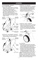
ASSEMBLY "QUICK RELEASE" HANDLES (ALL OTHER MODELS) • Raise lower handle section to mowing position and align holes in lower handle with holes in handle brackets. • Insert handle bolts through lower handles and handle brackets; secure with lower ("standard") knobs. • Remove protective padding, raise upper handle section into place on lower handle and tighten both upper ("quickadjust") knobs. Operator presence control bar LIFT UP MOWING POSITION 3 POSITION "EZ" HANDLES • Raise lower handle section to operating position and align hole in handle with one of three height positioning holes. • Insert handle bolt through handle and bracket and secure with knob. • Repeat for opposite side of handle. Bolt Knob Handle bracket LIFT Upper 3 POSITION "QUICK" HANDLES UP handle • Raise lower handle section to operating Upper handle knob ("quick- adjust") position and squeeze the bottom ends of lower handle towards each other until the pin in handle can be inserted into one of the three height adjustment Lower handle holes. Lower handle knob ("standard") SQUEEZE Handle pin 2 POSITION / "ADJUSTABLE" HANDLES • Raise handles until lower handle section locks into place in mowing position. Operator presence control bar LIFT UP MOWING POSITION Handle adjustment bracket ALL HANDLES LIFT UP Upper • Raise upper handle section into place handle on lower handle, remove protective pad- ding and tighten both handle knobs. • Remove handle padding holding operator presence control bar to upper handle. Handle knob • Your lawn mower handle can be adjusted for your mowing comfort. Refer to "ADJUST HANDLE" in the Service Lower handle and Adjustments section of this manual. NOTE: For shipping purposes, the rear wheels on your lawn mower may not be adjusted to the same position as the front wheels. Before operating mower adjust all wheels to the same cutting height. 6
-
 1
1 -
 2
2 -
 3
3 -
 4
4 -
 5
5 -
 6
6 -
 7
7 -
 8
8 -
 9
9 -
 10
10 -
 11
11 -
 12
12 -
13
-
14
-
15
-
16
-
17
-
18
-
19
-
20
-
21
-
22
-
23
-
24
-
25
-
26
-
27
-
28
-
29
-
30
-
31
-
32
-
33
-
34
-
35
-
36
 |
 |
