ProForm 2001 Exl Owners Manual - Page 19
Power, Board, Install, Power/isolation
 |
View all ProForm 2001 Exl manuals
Add to My Manuals
Save this manual to your list of manuals |
Page 19 highlights
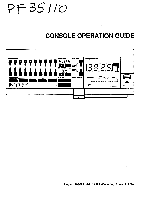
POWER BOARD HOW TO INSTALL THE NEW POWER/ISOLATION BOARD 1. Unplug the treadmill power cord. 2. Unplug the wires from the existing link/isolation board. 3. Remove the existing link/isolation board. 4. Install the new one-piece board. 5. Connect the small 2-condUctor wire to connector "P2." 6. Connect the 9-wire connector to the 9-pin header. The locking ramp on the wire harness should be placed toward the inside of the board, toward the plastic flange of the header. 7. Connect the three wires out of header "P3" to the motor controller: black to "L," white to "W" and red to "H." 8. Connect the white AC wires to "J1" and "J2." 9. Connect the black wire from the circuit breaker to "J3," "J4" or "LIVE." 10. Connect the black wire from the motor controller to "JX1" or to the top of the relay (black box) if a 1/4" connector spade is there. Part No. 109618 6/92 Printed in U.S.A. O 1992 Wesio,Inc. HOW TO INSTALL THE NEW POWER/ISOLATION BOARD 1. Unplug the treadmill power cord. 2. Unplug the wires from the existing link/isolation board. 3. Remove the existing link/isolation board. 4. Install the new one-piece board. 5. Connect the small 2-conductor wire to connector "P2." 6. Connect the 9-wire connector to the 9-pin header. The locking ramp on the wire harness should be placed toward the inside of the board, toward the plastic flange of the header. 7. Connect the three wires out of header "P3" to the motor controller: black to "L," white to "W" and red to "H." 8. Connect the white AC wires to "J1" and "J2." 9. Connect the black wire from the circuit breaker to "J3," "J4" or "LIVE." 10. Connect the black wire from the motor controller to "JX1" or to the top of the relay (black box) if a 1/4" connector spade is there. Part No. 109618 6/92 Printed in U.S.A. © 1992 Weslo.inc. . M6-2
-
 1
1 -
2
-
3
-
4
-
5
-
6
-
7
-
8
-
9
-
10
-
11
-
12
-
13
-
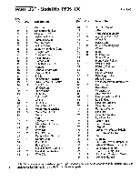 14
14 -
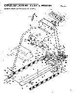 15
15 -
 16
16 -
 17
17 -
 18
18 -
 19
19
 |
 |
