ProForm 380 Razor Elliptical Uk Manual - Page 9
to the Pulse Wire 37 in the Right Pulse Bar
 |
View all ProForm 380 Razor Elliptical manuals
Add to My Manuals
Save this manual to your list of manuals |
Page 9 highlights
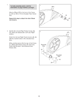
7. Slide the Console Cover (96) upward to the Console (4). Insert the console pulse wires downward through the Console Cover. Tip: Avoid pinching the wires. Attach the Console Cover (96) with four M4 x 16mm Round Head Screws (84). 7 4 Pulse Wires 96 Avoid pinching the wires 84 8. Identify the Left and Right Pulse Bars (5, 16), which are marked with "Left" and "Right" stickers. 8 Have another person hold the Right Pulse Bar (16) near the Upright (2). Connect the console pulse wire in the Upright (2) to the Pulse Wire (37) in the Right Pulse Bar (16). Tip: Avoid pinching the wires. Attach the Right Pulse Bar (16) to the Upright (2) with an M10 x 20mm Patch Screw (79) and an M10 Split Washer (78). Repeat this step for the Left Pulse Bar (5). 5 Pulse Wire 2 Avoid pinching the wires 37 78 79 16 9. Identify the Right Pedal (13), which is marked with a "Right" sticker, and orient it as shown. 9 Locate the bumper on the underside of the right Pedal Arm (14). Then, position the hole in a Pedal Bracket (15) over the bumper. Attach the Right Pedal (13) and the Pedal Bracket (15) to the right Pedal Arm (14) with four M8 Locknuts (82). Repeat this step for the Left Pedal (not shown). 13 14 Bumper 15 Hole 82 9
-
 1
1 -
2
-
3
-
 4
4 -
 5
5 -
 6
6 -
 7
7 -
 8
8 -
 9
9 -
 10
10 -
 11
11 -
 12
12 -
 13
13 -
 14
14 -
15
-
16
-
17
-
18
-
19
-
20
-
21
-
22
-
23
-
24
-
25
-
26
-
27
-
28
 |
 |
