ProForm 465 S Uk Manual - Page 6
Firmly, make sure, not to pinch the wires or cables, Do not tighten the Button Bolts yet., Make sure
 |
View all ProForm 465 S manuals
Add to My Manuals
Save this manual to your list of manuals |
Page 6 highlights
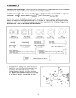
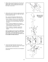
2. Whilst another person lifts the back of the Frame (1) slightly, attach the Rear Stabiliser (9) to the Frame with two M10 x 75mm Carriage Bolts (34) and two M10 Nylon Locknuts (33). 3. Whilst another person holds the Upright (2) near the Frame (1) as shown, connect the Upper Wire (44) to the Reed Switch Wire (53). Next, connect the Resistance Cable (45) to the Lower Resistance Cable (65) in the following way: • Refer to drawing A. Pull up on the metal bracket, and insert the tip of the Resistance Cable (45) into the wire clip on the Lower Resistance Cable (65) as shown. • Refer to drawing B. Firmly pull the Resistance Cable (45) and slide it into the metal bracket on the Lower Resistance Cable (65) as shown. • Refer to drawing C. Using pliers, squeeze the prongs on the upper end of the metal bracket together. Slide the Upright (2) onto the Frame (1); make sure not to pinch the wires or cables. Attach the Upright with two M10 x 74mm Button Bolts (67), two M10 Nylon Locknuts (33), and two M10 Split Washers (59). Do not tighten the Button Bolts yet. 4. Connect the Upper Wire (44) to the wire on the Console (23). Next, attach the Console to the Upright (2) with four M4 x 12mm Screws (42). Press the Resistance Knob (63) onto the Resistance Control (45). 2 33 1 3 2 33 9 34 Make sure not to pinch the wires or cables. 33 45 65 1 59 67 59 44 53 A B Metal Bracket 45 45 C 45 65 65 65 4 Console Wire 42 44 63 23 45 42 2 6
-
 1
1 -
 2
2 -
 3
3 -
 4
4 -
 5
5 -
 6
6 -
 7
7 -
 8
8 -
 9
9 -
 10
10 -
 11
11 -
 12
12 -
13
-
14
-
15
-
16
 |
 |
