ProForm 465 S Uk Manual - Page 7
M10.5 Washer 55 onto an M8 x 25mm Button Screw
 |
View all ProForm 465 S manuals
Add to My Manuals
Save this manual to your list of manuals |
Page 7 highlights
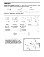
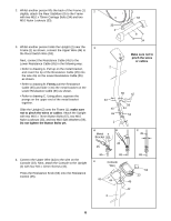
5. Identify the Left Handlebar (6), which is marked with a sticker. Insert the Left Handlebar into one of the 5 Handlebar Arms (5); make sure that the Handlebar Arm is turned so the hexagonal holes are on the indicated side. Attach the Left Handlebar to one of the Handlebar Arms with two M8 x 45mm Bolts (50) and two M8 Nylon Locknuts (38). Make sure that the Nylon Locknuts are inside of the hexagonal holes. Do not fully tighten the Bolts yet. Attach the Right Handlebar to the other Handlebar Arm (not shown) in the same way. 6 38 50 5 Hexagonal Holes 6. Apply a small amount of the included grease to the left and right axles on the Upright (2). 6 Identify the Left Handlebar (6), which is marked with a sticker. Slide a Frame Spacer (48), a Handlebar Spacer Grease 8 (47), the Left Handlebar, and a Handlebar Cap (46) onto the left axle on the Upright (2) as shown. Slide an M10.5 Washer (55) onto an M8 x 25mm Button Screw (56), and tighten the Button Screw into the axle. 48 47 6 Attach the Right Handlebar (8) in the same way. 46 55 2 56 7. Apply a small amount of grease to the axle on the left 7 Disc Crossbar (16). Slide the Left Pedal Arm (11) onto the axle and attach it with an M8.5 Washer (35) and an M8 Nylon Locknut (38). Insert the left Handlebar Arm (5) into the bracket on the end of the Left Pedal Arm (11), and attach it with a Pedal Arm Bolt Set (40). Repeat this step to attach the Right Pedal Arm (12). Refer to step 5. Tighten the M8 x 45mm Bolts (50) in 40 the Handlebar Arms (5). Tighten the two M10 x 74mm Button Bolts (67). 5 40 11 7 67 5 38 35 16 Grease
-
 1
1 -
 2
2 -
 3
3 -
 4
4 -
 5
5 -
 6
6 -
 7
7 -
 8
8 -
 9
9 -
 10
10 -
 11
11 -
 12
12 -
13
-
14
-
15
-
16
 |
 |
