ProForm 525 X Treadmill English Manual - Page 7
The Console May Be Damaged When
 |
View all ProForm 525 X Treadmill manuals
Add to My Manuals
Save this manual to your list of manuals |
Page 7 highlights
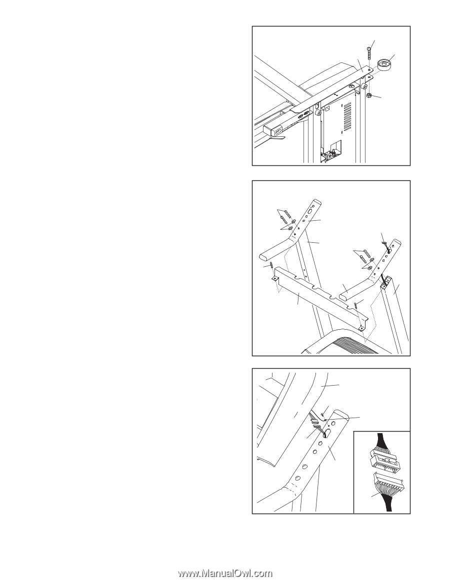
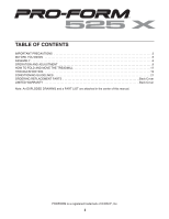
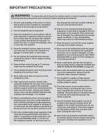
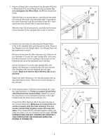
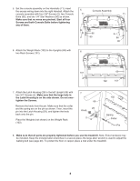
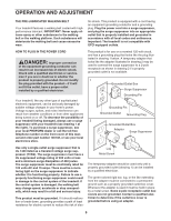
2. Attach a Wheel (66) to the base of the Uprights (69) with 2 a Wheel Bolt (64) and a Wheel Nut (32) as shown. Do not overtighten the Wheel Bolt; the Wheel should turn freely. With the help of a second person, carefully tip the treadmill onto its other side. See assembly step 1 and attach the other Extension Leg (63) and Base Pads (57). Next, attach the other Wheel (66) as described above. With the help of a second person, carefully tip the treadmill so the base of the Uprights (69) is flat on the floor. 64 69 66 32 3. Remove the two bolts (A) attaching the Weight Rack (102) to the Uprights (69), and discard the bolts. Remove the Weights from the Weight Rack. The Weight Rack will be assembled in step 6. Remove the tie from the Wire Harness (42). Hold one of the Handrails (71) near the right Upright (69), and insert the Wire Harness into the opening in the bottom of the Handrail and out of the indicated hole in the top. Set the Handrail (71) on the right Upright (69), and tighten two Extension Leg Bolts (93) with two Handrail Star Washers (95) into the Handrail and the right Upright. Make sure that the Wire Harness (42) is not pinched. Attach the other Handrail (71) to the left Upright (69) as described above. Note: There is not a wire harness on the left side. 3 93 95 A 102 71 42 69 93 95 71 69 A 4. Have another person hold the Console Base (47) near 4 the right Handrail (71). If there is a green ground wire extending from the Console Base, attach the end of the ground wire to the indicated small hole in the right Handrail with the Silver Ground Screw (75). Connect the Wire Harness (42) to the wire harness on the Console Base (47). Make sure to connect the connectors properly (see the inset drawing). The connectors should slide together easily and snap into place. If the connectors do not slide together easily and snap into place, turn one connector and try again. IF THE CONNECTORS ARE NOT CONNECTED PROPERLY, THE CONSOLE MAY BE DAMAGED WHEN THE POWER IS TURNED ON. 47 75 Ground Wire 42 71 42 7
-
 1
1 -
 2
2 -
 3
3 -
 4
4 -
 5
5 -
 6
6 -
 7
7 -
 8
8 -
 9
9 -
 10
10 -
 11
11 -
 12
12 -
13
-
14
-
15
-
16
-
17
-
18
-
19
-
20
-
21
-
22
-
23
-
24
-
25
-
26
 |
 |