ProForm 525 X Treadmill English Manual - Page 8
two Rack Screws 101.
 |
View all ProForm 525 X Treadmill manuals
Add to My Manuals
Save this manual to your list of manuals |
Page 8 highlights
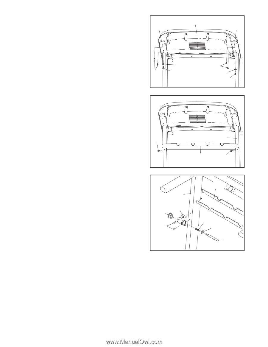
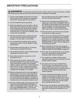
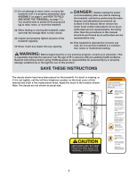
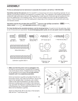
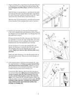
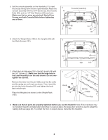
5. Set the console assembly on the Handrails (71); insert the excess wiring down into the right Handrail. Attach the 5 Console Assembly console assembly with four 3/4" Screws (2), two Console 71 71 Bolts (90), and two 1/4" Star Washers (96) as shown. Make sure that no wires are pinched. Start all four Screws and both Console Bolts before tightening any of them. 96 2 90 2 96 90 6. Attach the Weight Rack (102) to the Uprights (69) with 6 two Rack Screws (101). 101 69 102 101 7. Attach the Latch Housing (29) to the left Upright (69) with two 3/4" Screws (2). Make sure that the large hole in the Latch Housing is on the side shown. Do not overtighten the Screws. Remove the knob from the pin. Make sure that the collar and the spring are on the pin as shown. Then, insert the pin into the Latch Housing (29), and tighten the knob back onto the pin. Place the Weights (not shown) on the Weight Rack (102). 7 69 29 Knob 2 102 Spring Collar Pin 8. Make sure that all parts are properly tightened before you use the treadmill. Note: Extra hardware may be included. Keep the included allen wrenches in a secure place; the large allen wrench is used to adjust the walking belt (see page 20). To protect the floor or carpet, place a mat under the treadmill. 8
-
 1
1 -
2
-
 3
3 -
 4
4 -
 5
5 -
 6
6 -
 7
7 -
 8
8 -
 9
9 -
 10
10 -
 11
11 -
 12
12 -
 13
13 -
14
-
15
-
16
-
17
-
18
-
19
-
20
-
21
-
22
-
23
-
24
-
25
-
26
 |
 |