ProForm 530i Treadmill User Manual - Page 8
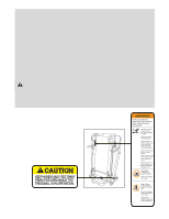
Nected Properly, The Console May Be Dam
 |
View all ProForm 530i Treadmill manuals
Add to My Manuals
Save this manual to your list of manuals |
Page 8 highlights
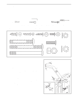
5. Attach the Console Back (95) to the console assembly 5 with five 3/4" Screws (6). Console Assembly 6 6 95 6 6. With the help of another person, hold the console assembly near the Right Upright (82) and the Left Upright (not shown). Connect the Wire Harness (83) to the wire harness in the console assembly. Make sure to connect the connectors properly (see the inset drawing); the connectors should slide together easily and snap into place. If the connectors do not slide together easily and snap into place, turn one connector and try to connect them again. IF THE CONNECTORS ARE NOT CONNECTED PROPERLY, THE CONSOLE MAY BE DAMAGED WHEN THE POWER IS TURNED ON. Insert the wire harnesses down into the Right Upright (82). Set the console assembly on the Right Upright (82) and the Left Upright (not shown). Thread two 1" Bolts (71) with 1/4" Star Washers (92) into each side of the console assembly. After you have started all four Bolts, tighten them. 7. With the help of another person, lower the console assembly (not shown) to the floor. Have the other person hold the treadmill steady during this step. Insert the two Wheels (108) into the Wheel Housings (106). Insert the Wheel Housings and the Wheels into the Base (109) as shown. (Note: It may be helpful to use a rubber mallet to fully insert the Wheel Housings.) Open part bag C. Attach the Wheel Housings to the Base with two Wheel Bolts (107) and two Wheel Nuts (21) as shown. Do not overtighten the Wheel Bolts. Center the Frame (54) between the Uprights (69, 82). Tighten the four 5/16" x 3 1/2" Bolts (93). Raise the Uprights (69, 82) to the vertical position. 6 Console Assembly 82 83 83 92 71 7 69 106 108 54 107 21 93 109 82 93 8
-
 1
1 -
2
-
 3
3 -
 4
4 -
 5
5 -
 6
6 -
 7
7 -
 8
8 -
 9
9 -
 10
10 -
 11
11 -
 12
12 -
 13
13 -
14
-
15
-
16
-
17
-
18
-
19
-
20
-
21
-
22
-
23
-
24
-
25
-
26
-
27
-
28
-
29
-
30
-
31
-
32
-
33
-
34
 |
 |
